At app 100-120 mA Laterals has a plateau where the thermals are slightly negative, this means no thermal drift an thus no need for the VBE.
Diodes are stiffer than resistors, when it comes to voltage over it, when you feed the drive in between two resistors and it pulls the midpoint up and down, then the two resistors generate their own signal, if you replace them with 2x2 LEDs you wil get 3 things, less current noise, stiffer drive and an automatic over current/short circuit protection, pls try in your simulations
Diodes are stiffer than resistors, when it comes to voltage over it, when you feed the drive in between two resistors and it pulls the midpoint up and down, then the two resistors generate their own signal, if you replace them with 2x2 LEDs you wil get 3 things, less current noise, stiffer drive and an automatic over current/short circuit protection, pls try in your simulations
Major differences are the Kmult, the combined TMC miller, and different values for the two gates on the laterals (R1 220) (R2 140) to compensate for the different Ciss of the N and P mosfets.
Also (for security only) I added a coil on the output.
Also (for security only) I added a coil on the output.
Attachments
So to have a little bit more of power I am now feeding the circuit with 42V (+-).
I am not sure the BC337 / 327 I am using in the mirror that carries current for the driving circuit, can easily cope with the voltage swing.
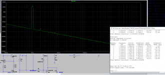
When at full power (84W) for Vin = 1.2VAC the voltage swing between collector and emitter of Q3 looks frightening.
Q3 Vce Max = 69V
Q3 Vce Min = 12V
Q3 Vce RMC = 45.5V
Q3 Power RMS = 284mW
Can the BC327 withstand the stress ?
All input is highly regarded as always.
I am not sure the BC337 / 327 I am using in the mirror that carries current for the driving circuit, can easily cope with the voltage swing.
When at full power (84W) for Vin = 1.2VAC the voltage swing between collector and emitter of Q3 looks frightening.
Q3 Vce Max = 69V
Q3 Vce Min = 12V
Q3 Vce RMC = 45.5V
Q3 Power RMS = 284mW
Can the BC327 withstand the stress ?
All input is highly regarded as always.
Attachments
The mirror Q3 & Q9 swing almost rail to rail when maximum output voltage is delivered.
You need devices that are good across the full rail to rail voltage and a bit to spare.
I'd suggest at least 160Vce0 devices, but you may get away with 100Vce0
But a mirror should use good Vsat performance.
I don't know which devices have both good Vsat and high Vce0.
You need devices that are good across the full rail to rail voltage and a bit to spare.
I'd suggest at least 160Vce0 devices, but you may get away with 100Vce0
But a mirror should use good Vsat performance.
I don't know which devices have both good Vsat and high Vce0.
Last edited:
Hello Frans
Would you explain your post ?
Yes, BD139-16 and BD140-16 (selected for gain)
16 is the gain grade of the BD139/140 BJTs
But is an 80V rated device suitable for +-42Vdc supplies which vary with mains voltage?
It seems to mee that there is some margin, but a quick simulation will reveal all (in this respect).
Simulation shows 6.7mA; 480mW max; 270mW AVG; Vce max 69vac; Vce 45Vrms.
I matched all mirror devices.
Trouble was to drill the initial BC pad holes to fit the bigger legs and I had to twist collector and base legs.
Allready made the mod and the ccs and mirror are working perfectly.
Yesterday received the TX.... now finishing the build.
Thank you guys.
I matched all mirror devices.
Trouble was to drill the initial BC pad holes to fit the bigger legs and I had to twist collector and base legs.
Allready made the mod and the ccs and mirror are working perfectly.
Yesterday received the TX.... now finishing the build.
Thank you guys.
I am curious ... why "Assemblage" power amp? You do know that is a brand name for a commercial tube amp kit line from Sonic Frontiers, right? The rights to that trademarked brand name is owned currently by Anthem.
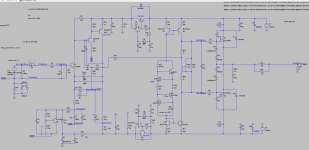
The design started with JG idea with opamp input, then evolved to a singleton IPS based on Bigun TGM8, then I included TMC Miller comp and changed the OPS to laterals. Droped the VBE multiplier and use a resistor for biasing.
I am living in Switzerland so now I speak French.... Here an Assemblage is a collection of wines and this amp is a collection of ideas..... No relation to any commercial product
")
Simulation shows 6.7mA; 480mW max; 270mW AVG; Vce max 69vac; Vce 45Vrms.
Be sure to drive the simulation into hard clipping when checking for these sorts of figures/margins.
Assemblage power amp evolution.....
Recently moved to the beautiful City of Bienne (Biel) and while looking for a new full time job after working as a professional loudspeaker designer for a major Swiss high end brand, I finally have some time to develop an evolution for this power amp.
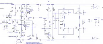
The input stage is based on the TGM8 retaining it's spectacular offset nulling circuit.
Last month I published a text describing the singleton IPS in Linkedin and asked Tim De Paravicini to comment.... He gracefully suggested cascoding the input device to lower distortion and although I was not successfully implementing his bootstrapped cascode due to issues regarding the offset stabilisation, I implemented another solution that works perfectly.
The original build has only two complementary laterals in the output with a 42V psu. It sounds organic with very good high freq detail and a nice enveloping low mid but I want more bass control so I doubled the output laterals and increased the psu to 56v.
After countless hours simulating this new design, I found that the floating CCS stability could be improved so there is a different approach from the excellent one proposed by FdW.
Due to the higher voltage of the psu I had to choose different transistors for the VAS and the VAS EF.
Maybe this design could even be bettered by using a more elaborate CCS as IPS load, but the added complexity is somehow overwhelming.
For now I am calling it the NP200.
I did not find the way to post big clear pictures in diyaudio threads so I am presenting also a pdf of the schematic hoping it is readable.
I did not have the time to create a models lib dedicated to this design so I am posting Myamp.txt and Cordell-Models.txt that should be placed in the same folder as the main .asc file so you can run the sim.
I hope some of you find the time to analyse the new sim and maybe propose corrections if found needed.
Recently moved to the beautiful City of Bienne (Biel) and while looking for a new full time job after working as a professional loudspeaker designer for a major Swiss high end brand, I finally have some time to develop an evolution for this power amp.
The input stage is based on the TGM8 retaining it's spectacular offset nulling circuit.
Last month I published a text describing the singleton IPS in Linkedin and asked Tim De Paravicini to comment.... He gracefully suggested cascoding the input device to lower distortion and although I was not successfully implementing his bootstrapped cascode due to issues regarding the offset stabilisation, I implemented another solution that works perfectly.
The original build has only two complementary laterals in the output with a 42V psu. It sounds organic with very good high freq detail and a nice enveloping low mid but I want more bass control so I doubled the output laterals and increased the psu to 56v.
After countless hours simulating this new design, I found that the floating CCS stability could be improved so there is a different approach from the excellent one proposed by FdW.
Due to the higher voltage of the psu I had to choose different transistors for the VAS and the VAS EF.
Maybe this design could even be bettered by using a more elaborate CCS as IPS load, but the added complexity is somehow overwhelming.
For now I am calling it the NP200.
I did not find the way to post big clear pictures in diyaudio threads so I am presenting also a pdf of the schematic hoping it is readable.
I did not have the time to create a models lib dedicated to this design so I am posting Myamp.txt and Cordell-Models.txt that should be placed in the same folder as the main .asc file so you can run the sim.
I hope some of you find the time to analyse the new sim and maybe propose corrections if found needed.
Attachments
-
MYamp.txt58.4 KB · Views: 42
-
nervine P200 EVO36 CASCODE IPS LED FLOATING CCS RESPONSE.asc25.5 KB · Views: 39
-
nervine P200 EVO36 CASCODE IPS LED FLOATING CCS NOISE.asc25.6 KB · Views: 37
-
nervine P200 EVO36 CASCODE IPS LED FLOATING CCS TIAN PROBE.asc26.4 KB · Views: 35
-
nervine P200 EVO36 CASCODE IPS LED FLOATING CCS OP.asc25.7 KB · Views: 37
-
 P200.JPG155.5 KB · Views: 123
 -
NP200 SCH.pdf141.4 KB · Views: 61
-
Cordell-Models.txt19.6 KB · Views: 40
- Status
- This old topic is closed. If you want to reopen this topic, contact a moderator using the "Report Post" button.
- Home
- Amplifiers
- Solid State
- Assemblage Power Amp