Dear Friends,
My interest in single supply low power <50W amplifiers started in the middle of 70s when I made a single channel of JLLH 15-20 Watt Class AB amp. I continued to use it for around 3-4 years.
When I saw Biguns single ended TGM8 started, I wanted to make a stereo amp of TGM8 with single supply. I made a request in his thread for such a retro mod of his TGM8 and he agreed to consider it.
I posted in his thread in post no 312 ( http://www.diyaudio.com/forums/soli...fier-based-rod-elliot-p3a-32.html#post3785052 ) a possible schematic and we had exchanged some PMs and he gave some suggestions.
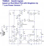
I made modifications to the original Schematic as per his suggestions and it is as posted below.
--gannaji
My interest in single supply low power <50W amplifiers started in the middle of 70s when I made a single channel of JLLH 15-20 Watt Class AB amp. I continued to use it for around 3-4 years.
When I saw Biguns single ended TGM8 started, I wanted to make a stereo amp of TGM8 with single supply. I made a request in his thread for such a retro mod of his TGM8 and he agreed to consider it.
I posted in his thread in post no 312 ( http://www.diyaudio.com/forums/soli...fier-based-rod-elliot-p3a-32.html#post3785052 ) a possible schematic and we had exchanged some PMs and he gave some suggestions.
I made modifications to the original Schematic as per his suggestions and it is as posted below.
--gannaji
Attachments
Here are answers to some of the questions raised by Bigun in our PMs.
- I will be interested in only through hole build. Using single power supply and output Elcos helps in DC protection of LS. That is my main reason.
- I am interested in building this amp. I have all the small signal semis and shall be procuring the 1943/5200 shortly.
- I will not be able to make PCB myself and an alternate arrangement has to be seen.
- I would prefer the power amp PCB seperate and PS PCB seperate. The Power spply can be similar to Dr Evils CM type with controlled rise time and fall time. This can reduce the risks of switch on thump as well as switch off unstability. This aspect requires to be studied in depth and a definitive solution found. In Bigun's thread on On / Off thumps, PMA suggested some good solutions.
- I would like the Amp Pcb to suit proper mounting of the Power BJTs on a heat sink of 196*100*33 mm. Ref http://www.diycomponents.in/ProductDetails.xhtml?current_SKU=1120 . Or 204*100*42 Ref: http://diyaudiocart.com/Heat-Sink-DAC-204-100
- These heat sinks are available easily in India. I hope either of them will be suitable for one channel.
- I was thinking a transformer sec voltage of 36 Volts AC (say 18-0-18) should be suitable giving audio output of 16 Volts AC and a power just above 30 watts into 8 ohms. Or a slightly higher voltage to give a max of 50 watts into 8 ohms.
--gannaji.
Last edited:
Member
Joined 2009
Paid Member
I'm not sure what R7 does either - I think it's redundant.
As for R8, it provides local 'nested feedback' from the VAS. It can be left off if you want to keep it as simple as possible.
I'm posting a picture of the schematic for easier viewing")
As for R8, it provides local 'nested feedback' from the VAS. It can be left off if you want to keep it as simple as possible.
I'm posting a picture of the schematic for easier viewing
Attachments
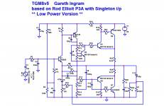
R24 & R27 can be any value from a 0r0 wire link to the 10r suggested.
Always leave pads for base stoppers in an unknown design.
You rarely know in advance whether the stopper effect will be required or not.
I would also allow base stoppers on drivers and if fitted pre-drivers.
The RC of C3 + R3 seems unusually low. Is this deliberate?
Allow pads to add D.Self compensating resistor between R13 and R17.
what is the purpose of resistors R7 and R8?
Dear maouna,
R7 is in the same place as R10 in your circuit, http://www.diyaudio.com/forums/soli...oop-stability-ltspice-my-amp.html#post3716602
The value is wrong and requires to be adjusted in relation to R10.
--gannaji
Last edited:
R24 & R27 can be any value from a 0r0 wire link to the 10r suggested.
Always leave pads for base stoppers in an unknown design.
You rarely know in advance whether the stopper effect will be required or not.
I would also allow base stoppers on drivers and if fitted pre-drivers.
The RC of C3 + R3 seems unusually low. Is this deliberate?
Allow pads to add D.Self compensating resistor between R13 and R17.
The various resistor and capacitor values are as per original Bigun's circuit, and are to be finalized. The circuit is posted as is to start off the discussion. Point about compensating R between R13 & R17 is noted. Thank you.
--gannaji
Last edited:
Comment of audiopip in the other thread http://www.diyaudio.com/forums/solid-state/242916-retro-amplifier-50-watt-circuit-4.html#post3798660 :
You might also consider PSRR. These old amps with a single supply have everything refered to the 0V rail. The + rail is protected by the bootstrap. As a result, coupled with the current amp config, I am not sure they don't work better than 'modern' direct coupled designs. The Armstrong 621 circuit is my favourite. A bit more complex but with better performance.
Will using a PNP for Q1 & NPN for Q2 and redrawing the circuit make any change to PSRR?
Member
Joined 2009
Paid Member
Unless operating with high power rail voltage it is probably a good idea to reduce the gain a little. Either increase R3 or decrease R10 - it's somewhat up to the constructor to choose what gain they want providing that the gain is not so low as to compromise stability without revisiting Cdom.
What would be a reasonable R10 value for the specified 50V rail? Around 1k0? Also, with these output devices, wouldn't it make more sense to specify a 70V rail to take advantage of these modern output transistors? A 50V rail is only going to give around 25W into 8R, which seems a waste.
If i have got it clear,the higher the value of this resistor,the lower the bandwith will be and and THD rises. On the contrary,the lower the value of this resistor,the higher will be the bandwith and THD drops. Rod Elliot uses a value of 10K in one of his amplifiers while other designers use lower values...
Member
Joined 2009
Paid Member
Hi Christian,
What you suggest (1k) sounds like a sensible value to me in terms of gain. Now, whether 25W is enough or not depends on your perspective. My DIY tube amplifier puts out perhaps 2W and has a gain of around 2. Actually it's pretty useless but mostly because of the low gain. Anyhow, I think 25W can be perfectly good. I look at it like this - most of the music we listen to (not talking about teenagers or parties here) will not need to go much above 1W on average. So it's the peaks in the music we worry about. The difference between 25W and 125W isn't as dramatic as it might seem. What the more powerful amplifiers have to their further advantage though is that some of the circuits are simply more linear with more volts across them when played mostly at lower levels. I think this is because there is less impact from the Early effect in BJTs - meaning that the current through the transistor doesn't just depend on the voltage between base-emitter but also on the voltage between collector-emitter. When the rail voltage is higher the collector-emitter voltage is usually higher too and then the signal represents a a smaller factional change than it would if the rail voltage were lower. This lower fractional change means the Early effect has less influence on the performance (which is good).
Hi Maouna,
Not sure which resistor you refer to, but the range of values we are talking about for the feedback network won't have any meaningful impact on the bandwidth except that a very low impedance feedback network will need a much larger capacitor in the shunt leg of the network.
What I was talking about earlier was the open loop gain in the audio range is higher when the feedback network has a lower impedance because the shunt resistor acts rather like emitter degeneration to the input device. So there is a tradeoff between needing a large capacitor and maintaining high open loop gain. I think the values we have been talking about should be fine even with some adjustments.
Rod uses a much higher value feedback resistor because he has an LTP front-end not a Singleton like the TGM8. With the LTP you have a high impedance feedback network because you are a) sending the feedback signal to the base of a transistor instead of an emitter, b) you want to match the impedance at the base of both transistors in an LTP for good dc-balance and since you want a highish input impedance to the amplifier you also want the same for the feedback signal.
The THD of this single rail amplifier will be higher than the fully enhanced TGM8, but that certainly doesn't mean it won't sound good. It may sound very good, but perhaps different from TGM8.
Some of these resistor values can be fine tuned later - I suggest that if the topology is good and sizes of the parts are known then the priority is to get a pcb designed. I'm not expert, I could give it a bash, but I've heard that 'Alex' is the guru for through-hole designs. Anybody else ?
Last edited:
dear Bigun,
Thank you very much for your comments and clarifications.
I had ordered and received the power transistors, a selected range of resistors, capacitors and Vero like perforated board (Shaans board). The Heatsinks will be reaching me in the next week. I am having the other transistors already.
To take the design forward, the latest schematic and LTsim file are enclosed. The numbering of the components is streamlined fully for the present.
As I was hoping 25 to 30 watts is adequate for me, 50V DC is adequate, requiring 63V caps for Power supply. I am having a Transformer, with 18-0-18V, 2A rating. This should give +50V DC,
I was hoping 2k2 (actually 4k7//4k7) and 100 ohms for the Feedback circuit should give adequate gain for the normal Line level input.
Can you kindly sim the total circuit for Distortion and Stability? My progress is very slow in learning LTspice.
Can you comment on the Dis profile versus the ratio of R13 to R14 and also the adequacy or otherwise of standing currents in Q1 and Q2? JLLH used much lower current in Q1, and also different polarity.
thanking you,
--gannaji.
Attachments
Last edited:
Member
Joined 2009
Paid Member
It's my fault - I was supposed to be helping out but a bunch of things happened at my end and I no longer have hobby-time available very often.
A few comments on post #16:
1/ C9 can be smaller, say 200uF,
2/ With C6 at 100pF this amp should be stable (unless you have a poor layout error). You should try reducing C6 and listen to the sound to see if you prefer a lower value (e.g. 68pF)
3/ C7 is too big by an order of magnitude, something around 33pF is better
4/ C12 might be larger for best performance, say 10,000uF
Otherwise I think what you have drawn looks good and I believe it will sound very good.
The transformer will give you more like 54V when there's no load applied and with a load this will drop to 48V - should be fine. If this gives you +/- 20V of useful swing into a speaker you can expect 25W rms power into an 8Ohm load.
If I get time I'll run your simulation.
Rgds,
Gareth
Dear Bigun,
Now, all parts required are procured.
I made the Schemati and layout in Diptrace and those files are enclosed.
The LT.asc file is also enclosed.
--gannaji.
I intend to make a prototype in shaan's way, with proto board.
Now, all parts required are procured.
I made the Schemati and layout in Diptrace and those files are enclosed.
The LT.asc file is also enclosed.
--gannaji.
I intend to make a prototype in shaan's way, with proto board.
Attachments
-
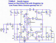 tgm8v5-lowpower retro V3-1.png61.4 KB · Views: 838
 -
DipTrace Schematic - TGM8-Retro V3-1.pdf42.6 KB · Views: 150
-
DipTrace PCB - TGM8-Retro V3-3.pdf55.3 KB · Views: 221
-
tgm8v5-lowpower retro V3-1.asc9.3 KB · Views: 99
-
TGM8-Retro V3-1.dch.txt136.7 KB · Views: 92
-
TGM8-Retro V3-3.dip.txt137.8 KB · Views: 95
Last edited:
Member
Joined 2009
Paid Member
Hi Ganaji,
I haven't seen software for making layout for proto-board before, looks pretty good. It will allow you to make some changes too if you want to try out some additional ideas. For example, you will find that changing Cdom (C6) will also affect the sound of the amplifier.
I'm not sure about your grounding scheme, you have a 'ground lift' resistor with back to back diodes in the 'ground rail' and I'm not sure that's where you want it.
Some people like to put a fixed value resistor in series with VR2 so that if VR2 is 'accidentally' adjusted to a low value the bias current won't be set too high and blow up the output too quickly.
Ranchu32 - I too have considered the use of a CFP VAS in order to improve linearity (referring to your suggestion in the TGM8 thread) and no doubt we have both heard Hugh suggest the same. I have simulated a CFP VAS in the past in different designs. Generally, I was dissappointed at the improvement but of course it requires to be built to hear the difference. I did put a CFP into the input (LTP at the time) and it made quite a difference to the sound - it was clearer, the bass had more punch, but the treble was not nice to my ears and I never used it again in the front end. In my TGM6 I did use a CFP VAS, but it was used to bootstrap the collector of the input device, just as I added a bootstrap to the input device of TGM8 - in this way there was a significant improvement in linearity in my simulations and the amplifier sounded way cleaner.
The thing about the VAS, if you read Dr. Self on this topic, is that with regular Cdom compensation you have a local feedback loop around the VAS device already which helps linearize it. Adding an EF buffer to the VAS allows Cdom to further linearize the VAS and gain a significant improvement. I have see the use of an EF buffer in many designs (including TGM8). The original JLH Class A amplifier does not use Cdom compensation (it uses slow output devices) and so perhaps in that design, the CFP VAS may offer something better than the buffered VAS ?
Anyhow, perhaps the first step is to see how good the simplest approach will work, without CFP VAS and then if interest persists, to try it as a change later on.
Last edited:
- Status
- This old topic is closed. If you want to reopen this topic, contact a moderator using the "Report Post" button.
- Home
- Amplifiers
- Solid State
- Bigun's TGM8 with Single Supply