Thanks Jason for so fast of a response..I have been looking at the screening on the board and the picture on post #48 and now your quick write up should make easier for me.
I'm still waiting on all of the resistor and mosfets..
I start with gluing Q1 and Q2 together and place other small components tomorrow..
Thanks
Cesar
I'm still waiting on all of the resistor and mosfets..
I start with gluing Q1 and Q2 together and place other small components tomorrow..
Thanks
Cesar
...
I start with gluing Q1 and Q2 together and place other small components tomorrow..
Thanks
Cesar
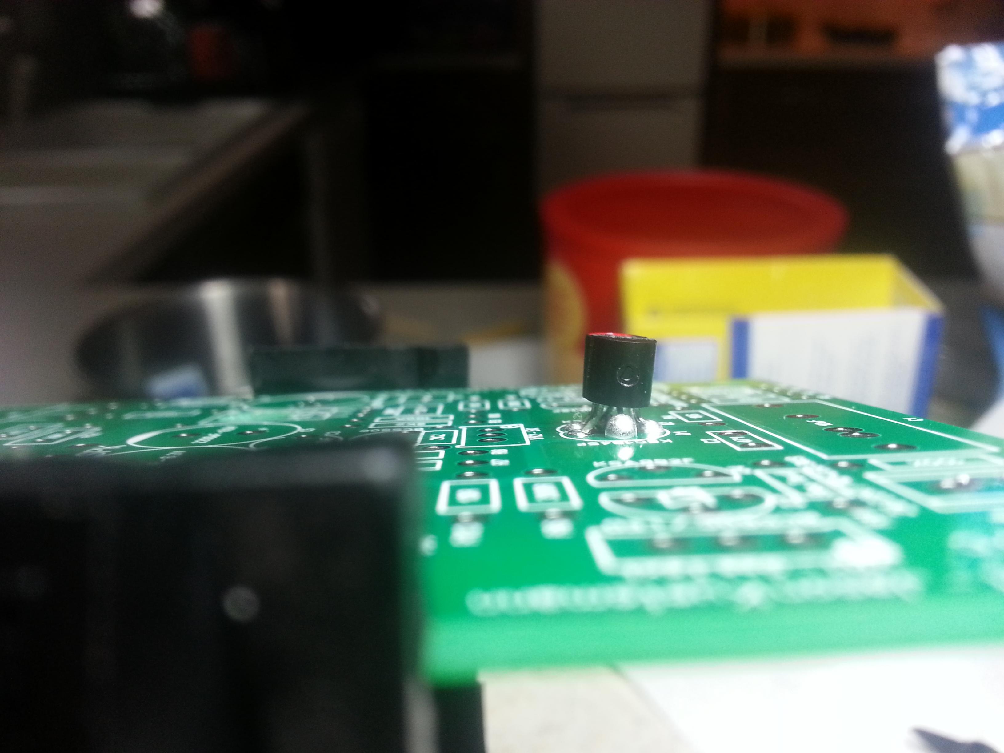
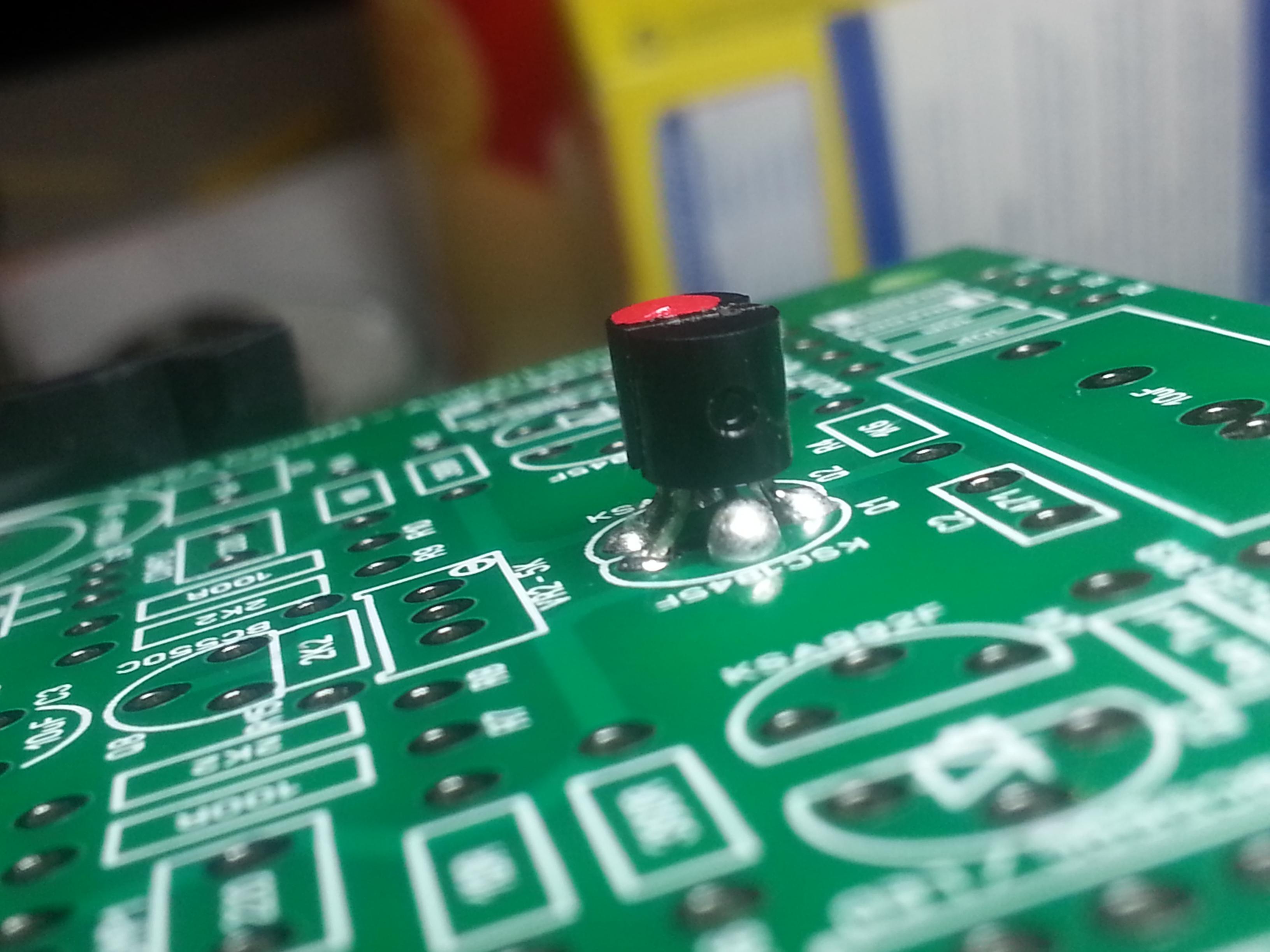
Just a reminder that you should use a little model paint or even a dab of nail polish to mark the top of one of the transistors and note which one that was. Reason being that once they are glued together you can't tell without checking them with a multimeter which is which. Hope that helps ensure the input pair gets oriented properly.
First attemp
This is the first time that I going to actually build a component as complicated as this. I’m someone who just likes to learn new things and love to listen to music not an electronic engineer. As I read about all this marvelous and wonderful components and how great sounding they are, and not having to spend thousands of dollars to get there. I said to myself I also can do and have these.
So today I take the plunge and start to build VASS Amp.
I have glue Q1 with Q2 and install it along with Q4 and Q5.
Since I’m a newbie at this I will go slowly and post photos. This way and can get feedback on how well or poor I’m doing.
Cesar
Attachments


So far so good Cesar.
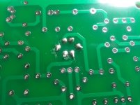
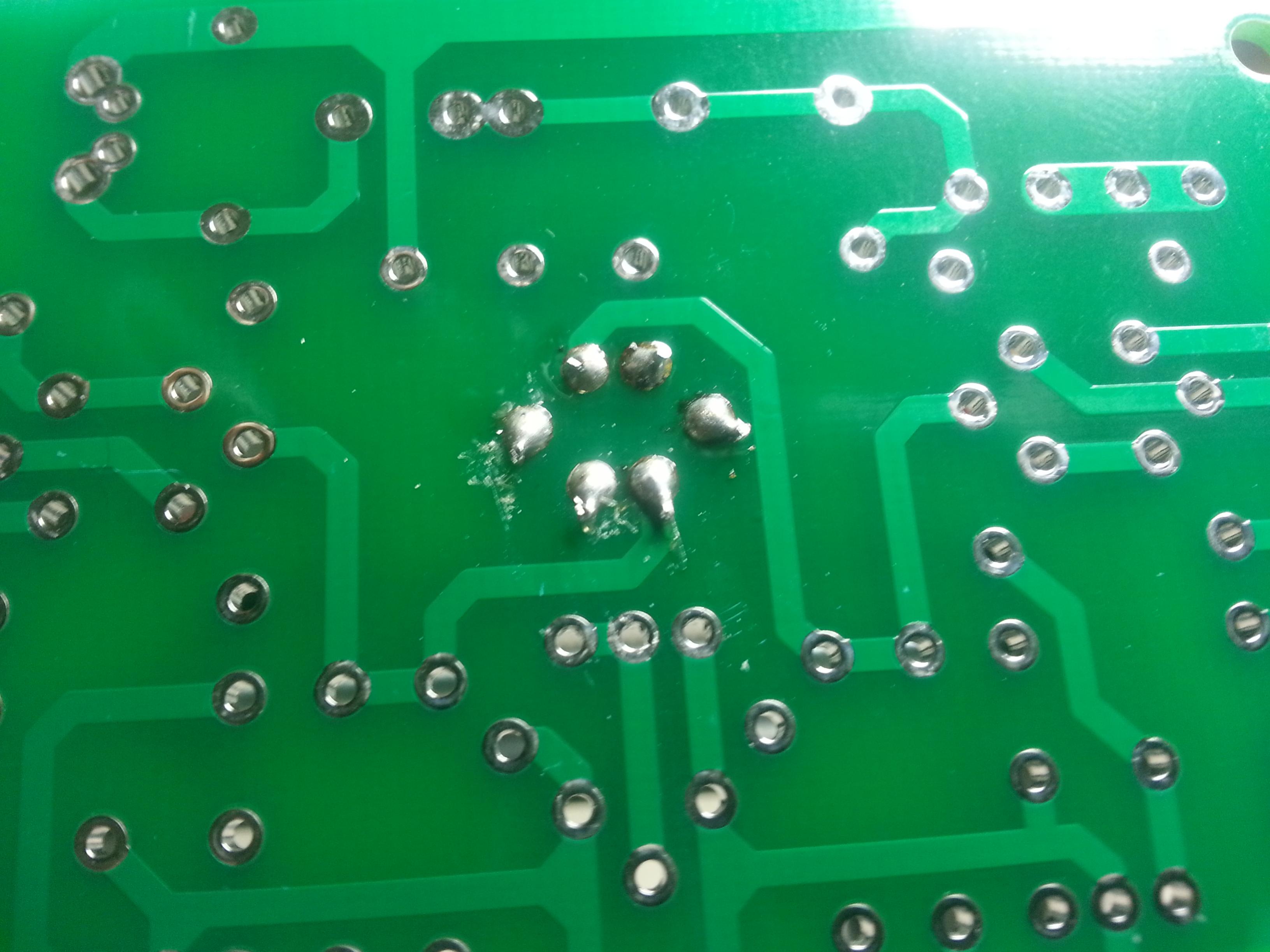
Go a little easier on the solder, you just need to see it 'wick' into the hole and make a nice little filleted joint. Remember that being double sided and plated holes you will have gravity and capillary action appear to make your solder disappear. This will trick you into putting too much on resulting in a large blob on the other side. Also, if you aren't using a thin rosin core solder for electronic work go get some. That will make controlling the amount you use easier.
If you could make the jump over to the other thread in the Solid State area <HERE> we can discuss progress there so I can concentrate on simple distribution of boards here, that would be great.
Thanks for allowing everyone to 'tag along' with your build, should be interesting.
I would re-solder the joins it looks like a blob solder
Go easy on Ceasar, he has stated it is his first build. So long as there are no shorts with excess solder he can leave it be for now. Hopefully with my prior tip the rest will look a little closer to ideal.
First attemp This is the first time that I going to actually build a component as complicated as this. I’m someone who just likes to learn new things and love to listen to music not an electronic engineer. As I read about all this marvelous and wonderful components and how great sounding they are, and not having to spend thousands of dollars to get there. I said to myself I also can do and have these.
So today I take the plunge and start to build VASS Amp.
I have glue Q1 with Q2 and install it along with Q4 and Q5.
Since I’m a newbie at this I will go slowly and post photos. This way and can get feedback on how well or poor I’m doing.
Cesar
Attached Thumbnails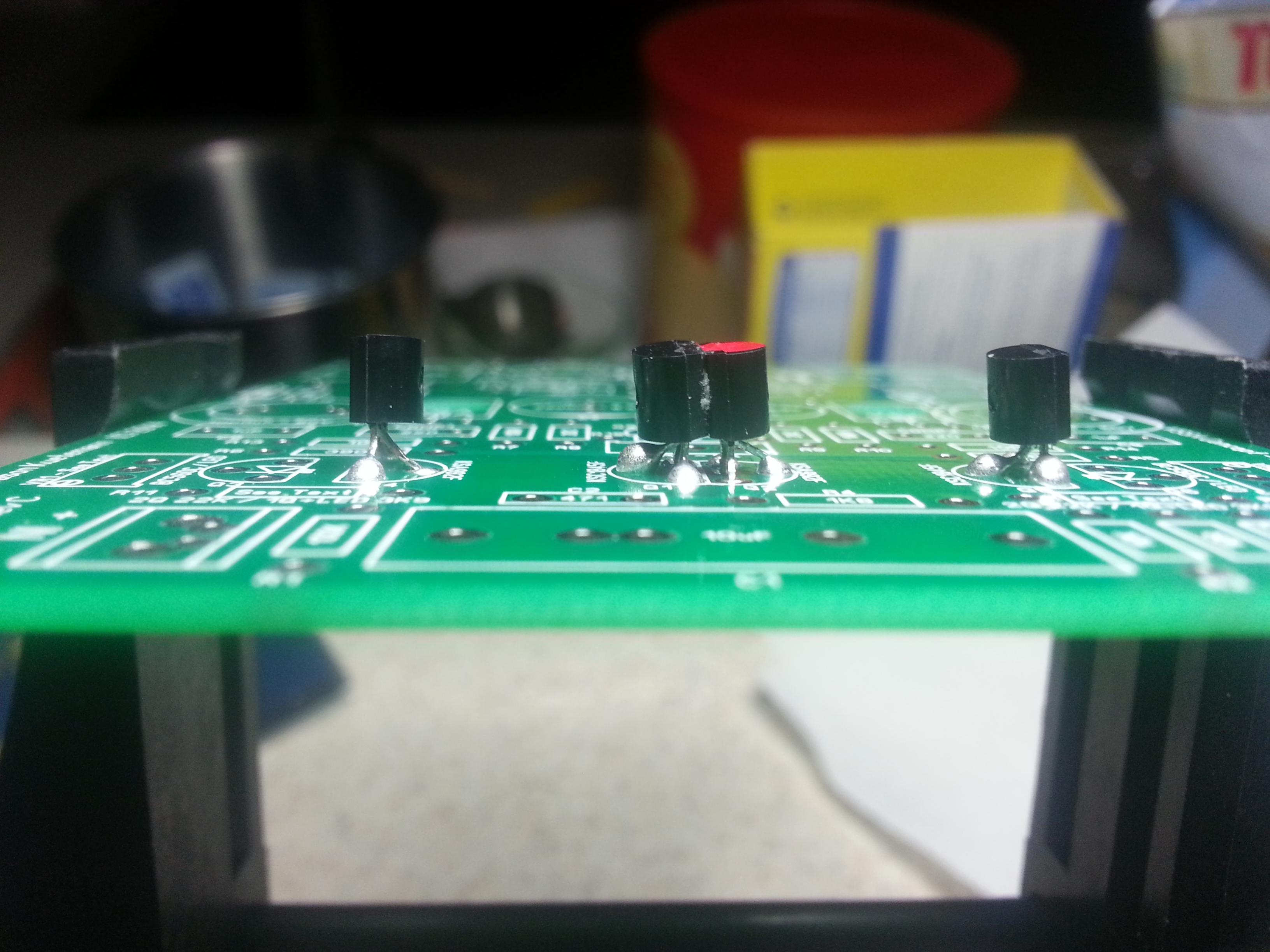


So today I take the plunge and start to build VASS Amp.
I have glue Q1 with Q2 and install it along with Q4 and Q5.
Since I’m a newbie at this I will go slowly and post photos. This way and can get feedback on how well or poor I’m doing.
Cesar
Attached Thumbnails


More Progress...
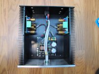
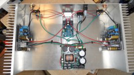
Slow going when you have to wait for small things like connectors and such. Got everything mounted into the chassis and just need input connectors and binding posts to arrive.
Dialled in to 120mA total current per module, <1mV offset and 14mA VAS current. I will see how warm it idles and may up the per module current to more like 160mA but I have to have it buttoned up before I make that decision.
Power supply is a Connexelectronic SMPS500Rv2 outputting +/-45V. I only had one issue - the soldering on the PSU output spades was so poor they came right off the board! Easy fix but still...
Attachments
Let´s start
I just started with my second diy work.... 🙂
I just started with my second diy work.... 🙂
Attachments

Last edited:
Nice work in a nice enclosure!!Slow going when you have to wait for small things like connectors and such. Got everything mounted into the chassis and just need input connectors and binding posts to arrive.
Dialled in to 120mA total current per module, <1mV offset and 14mA VAS current. I will see how warm it idles and may up the per module current to more like 160mA but I have to have it buttoned up before I make that decision.
Power supply is a Connexelectronic SMPS500Rv2 outputting +/-45V. I only had one issue - the soldering on the PSU output spades was so poor they came right off the board! Easy fix but still...
Congratulations.
Thimios.
Tight build there Sheldon, no wonder you were concerned about the dimensions.
@Everyone else - It is really nice to see other builds, please do continue to post progress or finished builds. I love to see different approaches and implementations
@Everyone else - It is really nice to see other builds, please do continue to post progress or finished builds. I love to see different approaches and implementations
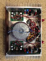
Don't worryMy build, not as neat.
With a few work you can do it excellent.
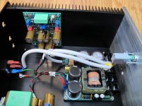
My Build. Was singing nicely, but had some very slight hiss. While re-wiring for that, i Killed Another SMPS 500r 😱 I guess i am not meant to use SMPS's. That is #3 for me. The only VSSA problem from that was 2 10r vas resistors. It is back up & singing on a Torrid & CM now. 🙂
Looks like these smps's are cheaper to just replace. Can't find anyone willing to try & repair them ( most say to cost prohibitive ).🙁
Looks like these smps's are cheaper to just replace. Can't find anyone willing to try & repair them ( most say to cost prohibitive ).🙁
Attachments
I wonder what happened to the SMPS? Mine is just the 300R but I blew an output on one channel and all that happened with the SMPS was that it cycled on and off. Once I solved the issue with the channel, the SMPS is working perfectly.
I would guess that is a speaker protection circuit from what is hooked up to it. An SMPS doesn't need soft start.
I would guess that is a speaker protection circuit from what is hooked up to it. An SMPS doesn't need soft start.
Thanks for answering. I think I see a pair of relays on the board. Is input signal tied to ground?
It appears he is using shielded cable with dual leads inside. Red wire for signal and black wire for signal ground. Then the shield is connected to the ground wire at the speaker terminal which in turn goes to start ground. I would guess that the shield is not attached at the other end.
Last edited:
- Status
- Not open for further replies.
- Home
- Amplifiers
- Solid State
- VSSA Through-Hole Version by Jason