Does anybody have any opinions on whether it would be possible to build an amp from Bryston’s service manuals? I have found the service manuals for the 3B up to 8B and the 7sst. Bryston states these schematics are the same as the Lexicon 212,225,312,412 and 501. Lexicon must have purchased the rights to use there technology.
I feel that I have read enough reviews now to get a handle on the sound of the amp. This amp does not have the liquid mid range of the pass labs Aleph amps. However, it makes up for this with a much deeper base and an extended distortion free high end, and there’s a lot less heat and a lot more power. It is basically a clean clear uncolored sound. In movies it must be good for rendering the sound of rain and braking glass. This amp is more akin to the Mark Levinson philosophy. It’s a complex multi-stage bipolar topology and it probably shares some of the sound qualities of Mark Levinson amps.
Looking at all these amps, the 7stt looks to be the best choice. It’s the newest and the output transistors in all the others are custom made for Bryston. The 7stt is a mono-block amp; however it contains two amp modules. They can be wired in series out of phase for more voltage or in parallel in phase for more current.
All Bryston amps use a variation on Bryson’s “Quad-Complementary” output section. This uses PNP and PNP transistors on both rails (see the schematic). I can and will post more on this later if the thread gets a good response. Over the years the schematic has not changed that much, but there are notable changes in the output stage.
I think for simplicity the clipping indicator module should be removed and the power supply is also going to need a bit of a trim. I’m not entirely shore if I can get away with removing the input section using the (DOA68) op amp (it’s not really an op amp chip) and just bypassing that section. The impedance of the amp hooking up the input right to r49 is less then 1k. This may have to be changed and is my biggest dilemma.
The schematic is attached below. It’s too big to be posted as a PDF. However if you look around, you’ll find it at http://www.bryston.ca/pdfs/7bsst_schematic.pdf
Attachments
I'd like to see some bryston projects. I use the 3BST and love it. The noise floor is bottomless. When people come over, and are suprised I have such an expensive amp, I turn the volume knobs up on my pre (ELAD) and have them put there ears to the tweeters. Dead silent at 135/channel. Not the tinyest bit of hiss.
I have build a 3B with good succes.
I have an original schematic ( sorry, don't have a scanner ) where the output transistors are labeled: 2n6609 and 2n3773.
The output devices in several 3Bs I've seen all have the manufacture code BR6522 and BR6521. Probably selected devices from motorola I believe.
However I used the 2n6031 and 2n5631 output devices in my amp and they work well.
For the PCB I made a xerox copy of an original, which can be pulled out quite easy, and made a copy of this to photo sensitive pcb.
I left out the clipping indicator, as LBHajdu suggest.
As the amp has a lot of negative feedback, layout and parts are critical. I have seen it oscillate a couple of times when tweeking the parts. Each time I had to replace the output devices as they fry easy when oscillating. After installing the 100nF cap across the output, which I had left out for some reason, the oscillations were over.
perfusionist,
I have looked at the reviews of this amp on www.audioreview.com I would say the reviews are more positive then negative. Because people use different equipment with the amps the reviews very, for example some people say it’s too bright some say it’s too dark. I don’t know where this amp falls into the audiophile food chain. It’s somewhere in the gray area between instrument amp / home theater amp / audiophile amp. In order to ensure the same noise floor in a diy amp grate care must be taken in the placement of the transformer and the wires running from it.
djmiddelkoop,
I’m happy to see that someone has already built this amp. You’ll find the schematics for the outdated st amps bundled in this document http://www.bryston.ca/pdfs/38bschem.pdf .I have two important questions I need answered.
2)
Does your diy amp include the board at the back of the amp with the op-amps made out of passive components? It should look something like the pic below.
1)
Besides the output power transistors (2n6031 and 2n5631) what else has to be thermally coupled to the heat sinks. Does the T0-220 devices driving the bases of the (2n6031 and 2n5631) have to be coupled? The bias stage uses one T0-92 device and one to-220 device if I have to guess I would almost certainly guess that the T0-220 has to be thermally coupled to the output devices.
I am a little bit skeptical about getting this amp to work. However I have a back-up, if this amp does not work I can build the Anthony E Holton N-channel Amplifier. It uses about the same rails, so I keep the power supply (the costly part) and replace the amp board. As you may have guessed, I’m interested in amps that use unusual topologies.
cowanrg,
If I remember correctly you’re using the pass labs aleph for you system. I can not recommend this amp for your back channel. The two channels should run as hot as your aleph, but unless you’re powering a movie theater it’s too much power. The sound of this amp will not be a good match with the aleph. It would be darker and more crisp (not as oozy).
L.B.Hajdu
Attachments
LB,
the answers to your questions:
2) no I did not include the opamp board
1) no the TO220 devices need not to be coupled to the output devices thermally in the 3B. They have a own heatsink in the 3B and in mine. They do not run very hot.
Ofcourse the TO92 in the bias need to be coupled thermally.
Thanks for the schematics link.
Dick.
Hey guys
The amp circuit is surprisingly simple for a $6000 amp.
I am seriously considering building one of these amps, but isnt it illegal?
Does anyone have internal pics of the amp? I want to find out if any of the transistors have to be thermally coupled to the output devices.
The amp circuit is surprisingly simple for a $6000 amp.
I am seriously considering building one of these amps, but isnt it illegal?
Does anyone have internal pics of the amp? I want to find out if any of the transistors have to be thermally coupled to the output devices.
Hi this has been somthing I have been thinking about for a while now ever since I found the PDF of all of the designs on the Bryston website.
What I would like to know is if anyone here who has already posted is onterested in doing a design for the PCB's for this project, as I han't quite got enough experience with protell yet to attempt something this complicated (and eagle just wouldn't cut it as far as something this big and complex goes). However, If things get to a stale point towards the summer when I have finised my work at uni for the year, I may be in a position to have a bash at trying to put something together (though I have no idea how it would sound, as I have only actualy made a few of my PCB designs to date).
What I would like to know is if anyone here who has already posted is onterested in doing a design for the PCB's for this project, as I han't quite got enough experience with protell yet to attempt something this complicated (and eagle just wouldn't cut it as far as something this big and complex goes). However, If things get to a stale point towards the summer when I have finised my work at uni for the year, I may be in a position to have a bash at trying to put something together (though I have no idea how it would sound, as I have only actualy made a few of my PCB designs to date).
hehe, ever look at the aleph2 schematic? i was like "where is the rest?" its pretty simple. but sometimes (most of the time), simple is better than complex.
and as far as being illegal/legal... as long as you arent selling it, you are fine. for your own use, its legal (this is my understanding). its like playing a cover song in your basement with your friends... but if you sell the cd without the band's permission, metallica will sue you.
and as far as being illegal/legal... as long as you arent selling it, you are fine. for your own use, its legal (this is my understanding). its like playing a cover song in your basement with your friends... but if you sell the cd without the band's permission, metallica will sue you.
lawbadman said:Hey guys
The amp circuit is surprisingly simple for a $6000 amp.
I am seriously considering building one of these amps, but isnt it illegal?
Does anyone have internal pics of the amp? I want to find out if any of the transistors have to be thermally coupled to the output devices.
djmiddelkoop,
That’s really surprising! Are you positive that it’s the TO92 device (2n5210) in the bias that needs to be thermally coupled and not the TO220 device (MJE180 (2))? I see what look to be a connector on the schematic but only for the TO220 device.
The low input Impedance of this thing without its buffer stage is going to be a problem. Did you make any changes to the input resistors to up it a little.
How does your amp sound and are you still using it today? Can you compare it to anything.
If I could pick any Bryston amp to build, it would be the 3B SST. From the reviews I red the 3b st is a sonic improvement over the 3b and the 3b sst is a sonic improvement over the 3b st. The main topology of these amps does not change much, if at all. There are some parts that have changed values and the output devices have changed as well as the input diff-pair devices. Other then that it’s still the same amp. Unfortunately I don’t have the schematic for the 3b stt. The only stt amp Bryston posted is the 7bstt.
I plan to leave out the outboard set of output devices. That will halve the wattage and I’m driving them unbalanced, once more cutting the wattage in half, so it should be about 120 watts in the end.
Below is the first draft of my PCB layout done in express PCB. It still needs some work.
Attachments
L.B. Hajdu,
the answers to your questions ( I hope ) :
1) Yes I'm sure. I'll try to make a picture of the original 3B I copied to show you.
2) I use 47k-ohm which is the same value the 3B uses.
3) when I connect it to my Acoustat electrostatic speakers it sounds a bit hard compared to the tube amplifier I use to drive these.
So I use it now bridged to drive my big subwoofer. This combination has powerfull deep bass.
4) I don't know about the st or sst versions.
Dick.
My understanding is that the 3B SST/4B SST/7B SST etc differ primamrily in the size of the power supply and the number of output devices.
As to the price tag, it really is very reasonable considering it is good enuff sonically to get Stereophile Class A, yet be a perfectly suitable PA amp with a 20 year warranty.
dave
As to the price tag, it really is very reasonable considering it is good enuff sonically to get Stereophile Class A, yet be a perfectly suitable PA amp with a 20 year warranty.
dave
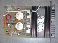
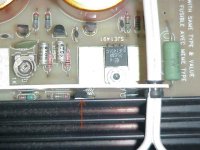
and here is a detailed picture of the TO92 bias regulator thermally coupled with heatsink compound to the heatsink of the output transistors, see red arrow.
Also visible (see also former picture) is the separate heatsink for the TO220 devices, barely touching the back of the TO92 bias regulator.
I also noticed that I mixed up the 2B and 3B, sorry for the misunderstanding.
So, for my previous entries, please read 2B iso 3B.
Dick.
Also visible (see also former picture) is the separate heatsink for the TO220 devices, barely touching the back of the TO92 bias regulator.
I also noticed that I mixed up the 2B and 3B, sorry for the misunderstanding.
So, for my previous entries, please read 2B iso 3B.
Dick.
Attachments
djmiddelkoop said:I mixed up the 2B and 3B
The original 2B was a bit "harder" at the top than the same gen 3B & 4B.
dave
Bryston just sent me the schematics for the 3bsst and 4b sst  , I never thought that they would send them to me after waiting for a week.
The only difference I could see from my quick glance is that the circuit for the 4b sst is the same as the 7b sst. The 3b sst has two pairs of outputs (as opposed to 4 pairs in the 4b sst) and a lower psu voltage. They are all basically the same amp.
, I never thought that they would send them to me after waiting for a week.The only difference I could see from my quick glance is that the circuit for the 4b sst is the same as the 7b sst. The 3b sst has two pairs of outputs (as opposed to 4 pairs in the 4b sst) and a lower psu voltage. They are all basically the same amp.
May I have a copy of the schematics ? what did you say to get them ?
L.B.Hajdu
LBHajdu@optonline.net
L.B.Hajdu
LBHajdu@optonline.net
Bryston!
May I have a copy too?
Thanks in advance.
Best regards,
Audiofanatic
LBHajdu said:May I have a copy of the schematics ? what did you say to get them ?
L.B.Hajdu
LBHajdu@optonline.net
May I have a copy too?
Thanks in advance.
Best regards,
Audiofanatic
If it's not too much trouble, can I also get a copy of the schematics?
ron.steinberg@sympatico.ca
Thanks!
Ron
ron.steinberg@sympatico.ca
Thanks!
Ron
- Status
- This old topic is closed. If you want to reopen this topic, contact a moderator using the "Report Post" button.
- Home
- Amplifiers
- Solid State
- Building Bryston amps from the service manuals