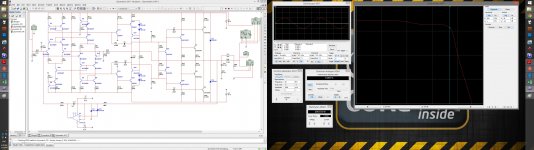
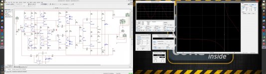
Just sketched a high-speed design using common-used transistors.
Minimal HF correction, high gain and linearity with open NFB. Low distortion at high frequencies (even at 50kHz not that bad).
At around 50W and 1kHz get 0.000 THD measurement (less than Multisim can measure)")
Probably will try to prototype and see what it sounds like...
Minimal HF correction, high gain and linearity with open NFB. Low distortion at high frequencies (even at 50kHz not that bad).
At around 50W and 1kHz get 0.000 THD measurement (less than Multisim can measure)
Probably will try to prototype and see what it sounds like...
Attachments


If you open schemstic and then hit "Full Screen" sign (bottom left corner) - it will be shown full size.
I have not built it yet, but I will do. Also very curious, how far it will go. Design is reletively high-current for maintaining speed, however this approach may compromise signal/noise ratio to some extent. Also, real b-c capacitances may bring some surprises...
We'll see
I have not built it yet, but I will do. Also very curious, how far it will go. Design is reletively high-current for maintaining speed, however this approach may compromise signal/noise ratio to some extent. Also, real b-c capacitances may bring some surprises...
We'll see
Complimentary "blameless" driving a beta enhanced Hawksford.
Interesting.
Drop the cascodes - simplify it ! led /2Q ccs + basic linn = fast.
It's still a VFA , more touchy compensation and it CAN'T come even
close in speed (cfa) .... It might be the fastest VFA, althrough.
PS- it might not have the PSRR of a standard "blameless".
OS
Interesting.
Drop the cascodes - simplify it ! led /2Q ccs + basic linn = fast.
It's still a VFA , more touchy compensation and it CAN'T come even
close in speed (cfa) .... It might be the fastest VFA, althrough.
PS- it might not have the PSRR of a standard "blameless".
OS
Last edited:
I'm not enthusiastic about operating BC550 transistors, rated for 50 volts, at (70/2) = 35 volts of Vce.
I'd suggest you consider operating the current source devices (such as Q5) at a Vce around 10 volts, and the cascode devices (such as Q24) at a Vce around 60 volts. I'd suggest you employ higher Vceo rated transistors (KSC1845? 2N5551? MPSA42?) in the cascode positions.
I'd suggest you consider operating the current source devices (such as Q5) at a Vce around 10 volts, and the cascode devices (such as Q24) at a Vce around 60 volts. I'd suggest you employ higher Vceo rated transistors (KSC1845? 2N5551? MPSA42?) in the cascode positions.
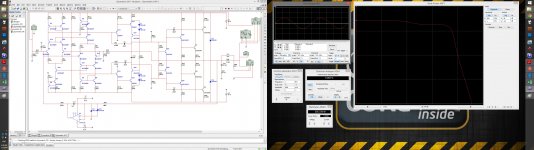
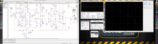
Open loop
Actually, I've tried that already - looks not bad. Conditions are the same as for simulation at the first picture in the initial post, but the input signal is -40db relative to that.
Many thanks to all of you for the comments - inspired some good ideas for moving further. Already preparing the live prototype. Also got an interesting idea for improving the pre-out stage - let me test it first
Run sim without AC feedback. (open loop gain/phase)
Actually, I've tried that already - looks not bad. Conditions are the same as for simulation at the first picture in the initial post, but the input signal is -40db relative to that.
Many thanks to all of you for the comments - inspired some good ideas for moving further. Already preparing the live prototype. Also got an interesting idea for improving the pre-out stage - let me test it first
Attachments
LTP + cascodes + Current Mirror + Emitter Follower+VAS + Hawksford cascodes => Instability will be a concern.
You will need to check inner loop carefully. Does Multisim do Tian probe or Middlebrook 2006 ("Final Solution") probe?
Best wishes
David
Unfortunatelu Multisim does not do those probes. But I'm trying to be careful with the inner loop
Stability is definitely a concern here and you never know how doon the models are, so live test can't be avoided I will build a prototype without the output stage first and check the behavior with open / closed NFB...
Complimentary "blameless" driving a beta enhanced Hawksford.
Interesting.
Drop the cascodes - simplify it ! led /2Q ccs + basic linn = fast.
It's still a VFA , more touchy compensation and it CAN'T come even
close in speed (cfa) .... It might be the fastest VFA, althrough.
PS- it might not have the PSRR of a standard "blameless".
OS
OS, CFA will probably be my next project - I see a lot of potential there!
I'm not enthusiastic about operating BC550 transistors, rated for 50 volts, at (70/2) = 35 volts of Vce.
I'd suggest you consider operating the current source devices (such as Q5) at a Vce around 10 volts, and the cascode devices (such as Q24) at a Vce around 60 volts. I'd suggest you employ higher Vceo rated transistors (KSC1845? 2N5551? MPSA42?) in the cascode positions.
Hi Mark, it was my concern initially as well, however my past esperience show bc550 / bc560 give very accurate / stable / identical results in many applications, including current sources. Plus, my thinking was that I will probably have less HF stability issues if I use transistors with the same high-frequency parameters it the input stage... I will test 2n5551 there anyway.
Cheers,
Valery
...Multisim does not do those probes.
Easy to download LTSpice and it's free.
Then you can do proper stability analysis.
And post your circuits for people to fix and/or learn from.
Do you realise that this circuit will not work in practice?I will build a prototype...
Search on VAS quiescent current instability or the abbreviation CMCL.
There has been extensive discussion.
Best wishes
David
Last edited:
Do you realise that this circuit will not work in practice?
That's exactly what the challenge is about - make it work...
I am aware of most of the problems I may face (at least I think so
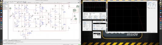
), it will require some practical testing and effort on arranging the right compensation, but it will work eventually. The question is how much speed will be left from the original design, but we'll see. It looks very promising.By the way, additional idea I mentioned earlier - is moving the pre-output stage EFs' to pure class A (adding 2 current soucces) decreases open loop THD more than 4 times (see attached).
Two key advantages:
1) Increased EF's linearity in general;
2) It makes VAS load more dinamically stable, decreasing intermodulation distortion.
Strongly recommend...
Attachments
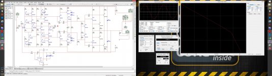
By the looks of it, the simulated open-loop response is firmly 2nd-order (i.e. phase shift close to 180°) by the time it approaches 0 dB. How do you expect this thing to be stable? And that's into a purely resistive load.
You're using a buffered VAS. Are you aware that the buffer may cause considerable common-mode distortion (being an EF operated very close to its lower rail)? A lot of it would cancel here, but still. In simulation, replacing the 2k2 emitter resistor by a CCS fixed that.
Basically a Class A driver stage is a good thing, but do check SOA and thermal requirements. Might be better suited for the first stage in an EF3.
...I am aware of most of the problems I may face (at least I think so
Perhaps not.
There are compensation/stability issues I mentioned and that you clearly have some ideas about.
There is also a quiescent current/bias stability problem with this type of circuit.
The complementary symmetry is an obvious and attractive idea that many people have tried.
The Current Mirrored + EF+VAS version that you have shown is not practical, too sensitive to imperfect balance.
Simple simulations look fine but a tiny mismatch will ruin it.
Search on this, there's plenty of discussion of how to deal with the problem - CMCL is one.
I should have pointed this out immediately but I expected that some one else already would have, Only when I had a little time I looked at the previous posts and saw no one had mentioned it.
Best wishes
David
Last edited:
Brain fart correction time:
Anyway, checking things with a nasty capacitive load is always a good idea. They tend to make outputs much slower if precautions are not taken, potentially up to the point of instability.
Oops! You don't need unity gain stability here, but rather 20 dB up or so. So open-loop response has to be firmly 1st order at 20 dB, which IIRC it also is.By the looks of it, the simulated open-loop response is firmly 2nd-order (i.e. phase shift close to 180°) by the time it approaches 0 dB. How do you expect this thing to be stable? And that's into a purely resistive load.
Anyway, checking things with a nasty capacitive load is always a good idea. They tend to make outputs much slower if precautions are not taken, potentially up to the point of instability.
- Status
- This old topic is closed. If you want to reopen this topic, contact a moderator using the "Report Post" button.
- Home
- Amplifiers
- Solid State
- XHS - Xtra High Speed Design