Live Prototype
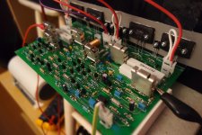
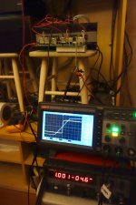
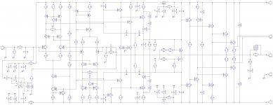
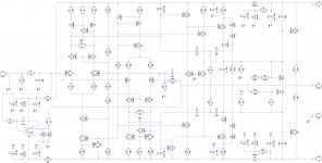
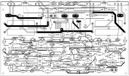
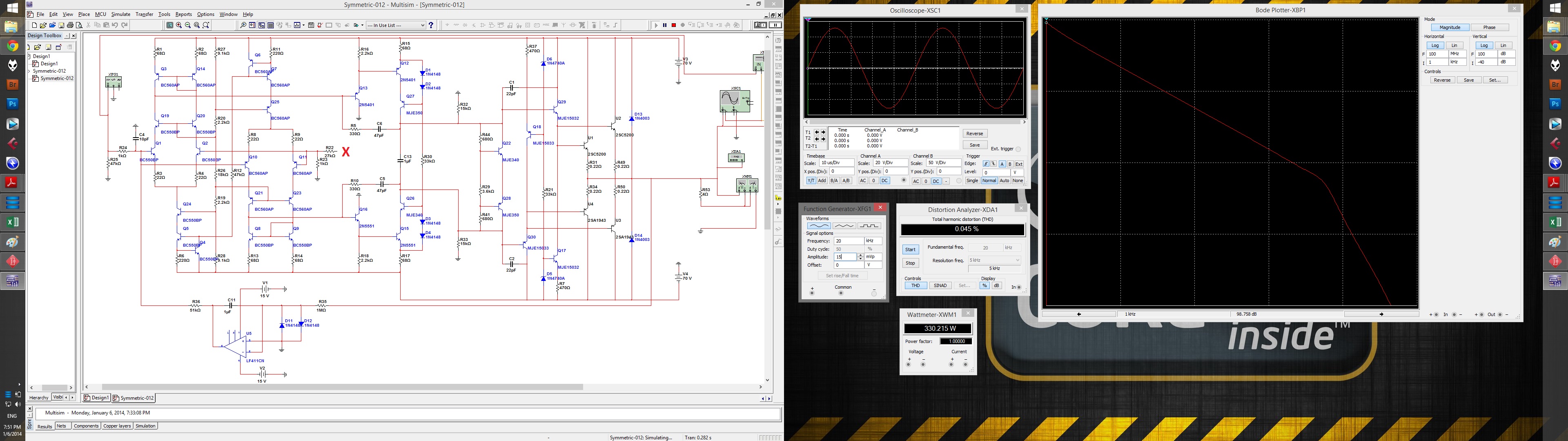
OK, made some improvements, played with simulation and finally made a live prototype. Schematic and some pictures are attached. PCB looks rather similar to my previous "PowerAmp Pio" design, but it is 1.5 times bigger in fact (much more transistors are employed).
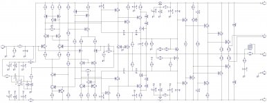
Fully symmetric design, low noise bc550/560 at the input, as initially planned.
Added CMCL, as Dave recommended. Tested with no CMCL - it is still balanced and working, but CMCL gives much more stability in case of higher elements tolerance - tried to dis-balance it a number of ways - with CMCL it is definitely more "self-balancing".
Initially planned TMC compensation required additional lag compensation capacitors in both VAS and pre-driver stages.
This was a "quick and dirty" approach I used to stop oscillation at around 5.5 MHz. So I am going to work on compensation more accurately to keep it minimal. Suggestions are welcome.
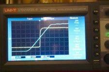
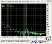
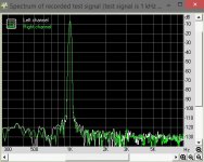
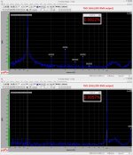
Anyway, even "as is", it is a great sounding amplifier. THD at 1kHz is around 0.0015% at 100W output power, slew rate is around 30V/uS, measured at the full amplitude (120V). Dominant harmonic is 2-nd, all the higher-ones are 10+ db lower amplitude.
OK, made some improvements, played with simulation and finally made a live prototype. Schematic and some pictures are attached. PCB looks rather similar to my previous "PowerAmp Pio" design, but it is 1.5 times bigger in fact (much more transistors are employed).
Fully symmetric design, low noise bc550/560 at the input, as initially planned.
Added CMCL, as Dave recommended. Tested with no CMCL - it is still balanced and working, but CMCL gives much more stability in case of higher elements tolerance - tried to dis-balance it a number of ways - with CMCL it is definitely more "self-balancing".
Initially planned TMC compensation required additional lag compensation capacitors in both VAS and pre-driver stages.
This was a "quick and dirty" approach I used to stop oscillation at around 5.5 MHz. So I am going to work on compensation more accurately to keep it minimal. Suggestions are welcome.
Anyway, even "as is", it is a great sounding amplifier. THD at 1kHz is around 0.0015% at 100W output power, slew rate is around 30V/uS, measured at the full amplitude (120V). Dominant harmonic is 2-nd, all the higher-ones are 10+ db lower amplitude.
Attachments
2-nd Harmonic
Hi All,
Output stage with class A drivers showed excellent results at the prototype (quiescent current 120-140 mA per output transistor). So let's put it aside for a while, leaving everything else, including differential input stage, EF, VAS and pre-driver EF (schematic is attached).
FFT of 1 kHz signal shows pretty low THD, purely consisting of 2-nd harmonic - around 0.0015% (all the higher harmonics are at the noise level - see attached screenshot).
2-nd harmonic is normally caused by some disbalance (assymetry) within the amp. I have checked many possible causes, trying to adjust the balance of each stage, however it is still there, at rourhly the same level.
Any ideas on what could be the cause?
Attachments
2-nd harmonic is normally caused by some disbalance (assymetry) within the amp. I have checked many possible causes, trying to adjust the balance of each stage, however it is still there, at rourhly the same level.
Any ideas on what could be the cause?
The top mirror (Q3 + Q8) is loaded by Q6 and Q22. The bottom mirror is loaded by Q7 and Q21. These are part of your problem.
The base current of Q6 flows into the mirror while the base current of Q22 flows out of the mirror. Thus the mirror is unbalanced by (|Ib6| + |Ib22|).
Another source of error is the mismatch in VCE between Q3 and Q8. Thanks to the Early effect, collector current varies with VCE; different VCEs cause different collector currents. In a mirror, different collector currents are undesirable.
Similar remarks could be made about the bottom mirror (Q13 + Q18) and its loads (Q17 + Q21).
The schematic of the uA741 integrated circuit opamp (1969) offers some ideas. Its current mirror (Q5 + Q6) is loaded by Q7 and Q15. The designer has taken pains to make sure Q7 and Q15 are the same polarity (both are NPN). Thus their base currents have the same sign. Furthermore, Q7 and Q15 are arranged to have the same emitter resistances (R3 = R12). Thus Q7 and Q15 have equal emitter currents. Thus they have equal base currents. Therefore the base currents of Q7 and Q15 do not unbalance the mirror. If you ask me, that's pretty elegant. And they did it 4 years before SPICE was written.
..
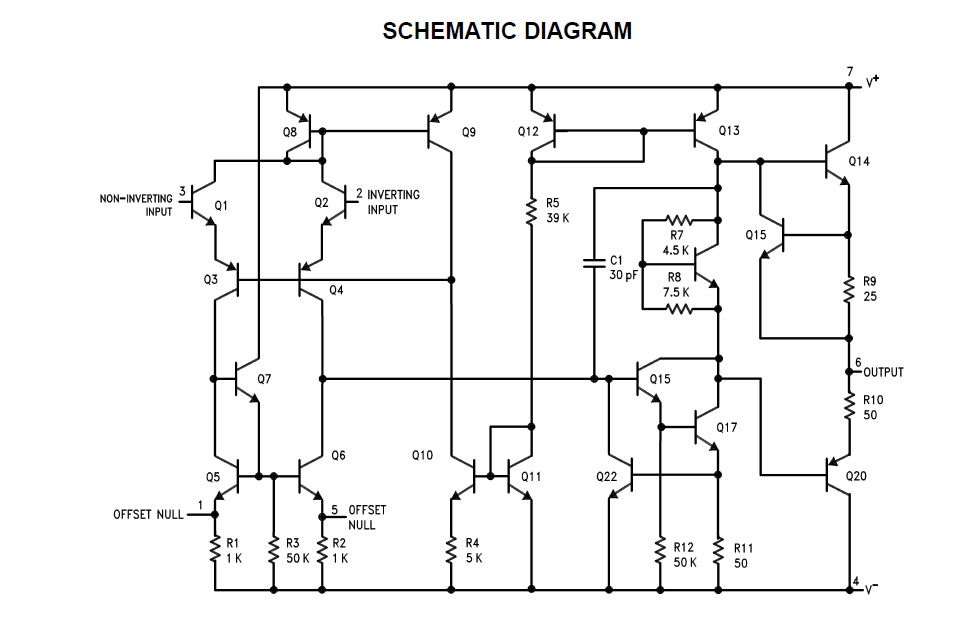
If you ask me, that's pretty elegant. And they did it 4 years before SPICE was written.
Mark, thank you - this is very elegant indeed.
In my case - I've tried to change EF topology to more traditional option with emitter connected to the rail through resistor, same as CMCL one in the mirrors (1k). It showed very close results, but appeared much less stable - quiescent current of VAS was slowly fluctuating, so that THD increased from time to time when current went below 2-3 mA. The other drawback was clipping - hard, with comprehensive artefacts.
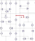
At that time I have found a "typo" mistake in my PCB (I had it right in the Multisim model, but then I had to manually copy the schematic to DipTrace for PCB design) - fragment is attached. Not a big deal in this topology, but certain disbalance between the top and bottom LTPs' tail currents was there.
So I have reverted back to my initial design with EFs loaded by current sources. Actually, those current sources make EFs' base currents stable, minimizing dinamic influence on mirrors' disbalance.
As a result - see the spectre. Also - no VAS quiescent current fluctuations and very soft, flat clipping.
Now I'm pretty satisfied
")
Thanks again for advice!
Attachments
Nico, this is actually a good question
You're right, this was a sort of "sport" interest to push VFA design a little bit to the limit, making it fast enough and low distortion at the same time. It was also interesting to practically test the A-class drivers. In my previous design (the one, I am building at the moment in 7 channels - see it here PowerAmp Pio - 7 channel) I used bryston-type-of output stage topology, which I like a lot.
As soon as I finish a 7-channel one, I will build a stereo amp based on this XHS design.
Yes, I'm that type of guy
Updated docs
Here are the final version docs on this project.
Cheers,
Valery
Here are the final version docs on this project.
Cheers,
Valery
Attachments
... exemplary distortion performance at 0.000001%
How do you arrive at this?
The distortion is almost buried in the noise but the 3rd is more that 110 dB and less than 120 dB down.
So about 0.0002%, or 200 times worse than your number, yes?
Still not to complain
Here are the final version docs on this project.
Hi Valery
The 1 kHz results are too low to be reliable, do you have any results for THD at 20 kHz, or 19 kHz + 20 kHz IMD?
I still don't think you have a CMCL but I need to think more about the effect of the current loaded EF ahead of the VAS.
As pointed out, it unbalances the current mirror but I simulated and this seems to be less important than I expected.
In fact I had less distortion when the mirror was unbalanced a little, not yet sure why.
Best wishes
David
How do you arrive at this?
The distortion is almost buried in the noise but the 3rd is more that 110 dB and less than 120 dB down.
So about 0.0002%, or 200 times worse than your number, yes?
Still not to complain
Hi Valery
The 1 kHz results are too low to be reliable, do you have any results for THD at 20 kHz, or 19 kHz + 20 kHz IMD?
I still don't think you have a CMCL but I need to think more about the effect of the current loaded EF ahead of the VAS.
As pointed out, it unbalances the current mirror but I simulated and this seems to be less important than I expected.
In fact I had less distortion when the mirror was unbalanced a little, not yet sure why.
Best wishes
David
Hi David, in fact I did those measurements before I have upgraded my measurement system, so I don't consider them reliable either, though distortion level was really low anyway.
I will re-measure it in a couple of days - I am going to use its OPS for testing my hybrid front-end and compare distortion level and sound impression of both front-ends with the same OPS.
We'll see
Cheers,
Valery
P.S. I'm sure there's no LOOP back to LTPs, so it's not really a CMCL, you are right, however those helper transistors definitely reduce common mode dis-balance down to acceptable level... then DC servo takes care of all the rest
...my measurement system, so I don't consider them reliable either...
What is your new measurement system?
Unreliability at such low levels hardly matters, but it's fun as an intellectual problem is it not?
however those helper transistors definitely reduce common mode dis-balance down to acceptable level... then DC servo takes care of all the rest
Yes, I expect the helper transistors should reduce the common mode imbalance.
But the servo only takes care of the differential mode I think.
So the common mode stability is a result of other factors.
Your test with the conventional EF assisted VAS showed worse stability.
You mentioned a PCB "typo" error connection, that was not on this test?
Best wishes
David
Measurements - XHS
I have bought a Dr-Jordan-Design software (German) and reconfigured my E-MU 1616M card in a better way. However, In about a month, I'm going to switch to Linx L22 - much wider bandwidth and even lower distortion one.
As far as I remember, I have corrected PCB mistake before testing conventional EFs. That mistake mostly contributed to the 2-nd harmonic, as the top and bottom LTPs had slightly different quiescent currents, leading to certain overall dis-balance of the circuit.
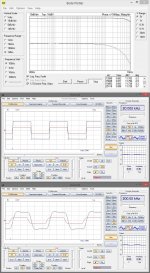
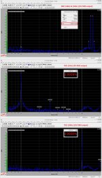
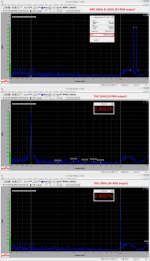
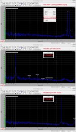
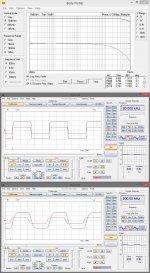
I have re-measured the key parameters, mostly at 3V, 10V and 20V RMS output swings, 1KHz and 10KHz, as well as IMD for 14KHz & 15KHz simultaneous signals, plus Bode and square waves @ 20KHz and 200KHz.
I refused from measuring THD @ 20KHz as the results would be really unreliable, I also could not measure IMD for 20V due to certain software limitations. Anyway, I think the results are representative enough.
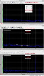
I will post the results of exactly the same measurements for my hybrid (tube IPS) front-end for comparison. They appeared very, very close. Major difference - overall noise level. In this symmetric design, s/n ratio exceeds 120db, in the hybrid one it's around 10db less (though it's still higher than 110db - no problem). Both front-ends show rather high slew rate - rise/fall times are 400nS in both cases, mostly limited by the input filter (in fact, the circuit is even more high-speed). Also, at the bottom top corner of the Bode plot, you can see the phase shift measurements at the frequencies close to 20KHz.
In both cases only the front-ends were tested, without OPS. Testing with OPS and real load is planned for the weekend. Stay tuned
Cheers,
Valery
P.S. Don't forget to press the "Full size" button in the bottom left corner of each image
What is your new measurement system?
Unreliability at such low levels hardly matters, but it's fun as an intellectual problem is it not?
Yes, I expect the helper transistors should reduce the common mode imbalance.
But the servo only takes care of the differential mode I think.
So the common mode stability is a result of other factors.
Your test with the conventional EF assisted VAS showed worse stability.
You mentioned a PCB "typo" error connection, that was not on this test?
Best wishes
David
I have bought a Dr-Jordan-Design software (German) and reconfigured my E-MU 1616M card in a better way. However, In about a month, I'm going to switch to Linx L22 - much wider bandwidth and even lower distortion one.
As far as I remember, I have corrected PCB mistake before testing conventional EFs. That mistake mostly contributed to the 2-nd harmonic, as the top and bottom LTPs had slightly different quiescent currents, leading to certain overall dis-balance of the circuit.
I have re-measured the key parameters, mostly at 3V, 10V and 20V RMS output swings, 1KHz and 10KHz, as well as IMD for 14KHz & 15KHz simultaneous signals, plus Bode and square waves @ 20KHz and 200KHz.
I refused from measuring THD @ 20KHz as the results would be really unreliable, I also could not measure IMD for 20V due to certain software limitations. Anyway, I think the results are representative enough.
I will post the results of exactly the same measurements for my hybrid (tube IPS) front-end for comparison. They appeared very, very close. Major difference - overall noise level. In this symmetric design, s/n ratio exceeds 120db, in the hybrid one it's around 10db less (though it's still higher than 110db - no problem). Both front-ends show rather high slew rate - rise/fall times are 400nS in both cases, mostly limited by the input filter (in fact, the circuit is even more high-speed). Also, at the bottom top corner of the Bode plot, you can see the phase shift measurements at the frequencies close to 20KHz.
In both cases only the front-ends were tested, without OPS. Testing with OPS and real load is planned for the weekend. Stay tuned
Cheers,
Valery
P.S. Don't forget to press the "Full size" button in the bottom left corner of each image
Attachments
Measurements - Hybrid with tube
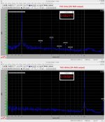
As promised, here goes exactly the same set of measurements, in the same conditions, with the same power supply, for my new Hybrid front-end for comparison. See more detailed description in the previous post.
Cheers,
Valery
As promised, here goes exactly the same set of measurements, in the same conditions, with the same power supply, for my new Hybrid front-end for comparison. See more detailed description in the previous post.
Cheers,
Valery
Attachments
Is it possible to open these files with DIP Trace ?Here are the final version docs on this project.
Cheers,
Valery
If not, what program should I use / download to open it ?
Cheers,
Ziggy.
Is it possible to open these files with DIP Trace ?
If not, what program should I use / download to open it ?
Cheers,
Ziggy.
Hi Ziggy, you can open those with p-cad viewer (freeware), however I can send you the original DipTrace files to your private e-mail.
Cheers,
Valery
there is already multisim file photo http://www.diyaudio.com/forums/atta...024609t-xhs-xtra-high-speed-design-xhs-21.jpg, Can Author please post multisim file.vedmitraa@gmail.com.
there is already multisim file photo http://www.diyaudio.com/forums/atta...024609t-xhs-xtra-high-speed-design-xhs-21.jpg, Can Author please post multisim file.vedmitraa@gmail.com.
Hi Vedmitraa, yes, I was already thinking about making your life easier
The model is sent to your e-mail.
By the way, if you manage to find (or make) the better models for Sanken devices - I will very much appreciate if you can share them. The ones I use are rather generic ones, and though the results they give are close enough to reality, having the better models would be useful.
Cheers,
Valery
- Status
- This old topic is closed. If you want to reopen this topic, contact a moderator using the "Report Post" button.
- Home
- Amplifiers
- Solid State
- XHS - Xtra High Speed Design