Hi boris
Can you share the attenuation circuit that used for sound card input?
Best regards.
Thimios.
You need potentiometer and optional two zeners to protect input of the sound card.
legs 1 and 3 to the load and leg no 2 to sound card -- thats it. To protect the sound card input just putt zeners across pin 2 and ground.
If you will have some artefacts put 10R resistor to separate signal GND from amp GND.
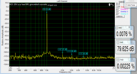
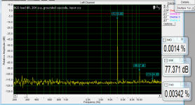
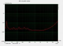
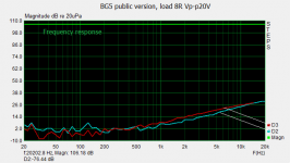
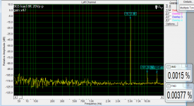
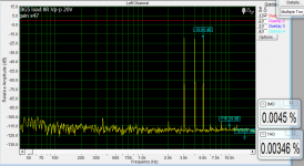
I have made small changes and will prepare a final pcb. Nearly all produsct are going 100dB bellow signal - so it is good enough. Amp has good parameters from low output till clipping - all power spectrum.
Attachments
I have made small changes and will prepare a final pcb. Nearly all produsct are going 100dB bellow signal - so it is good enough. Amp has good parameters from low output till clipping - all power spectrum.
Nice parameters,
Regards
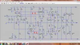
The BG4 was with 2 LTP's at the front of the amp (development has stopped cause lack of my knowlage to sort out clipping issues). BG5 is version with single j-fet LTP at the front of the amp. So far it looks like on schematic bellow.
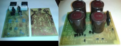
I just substituted two zeners in cascode with double leds. After I will do all tests Ill post whole documentation anyway.
Regards
I just substituted two zeners in cascode with double leds. After I will do all tests Ill post whole documentation anyway.
Regards
Attachments
Last edited:
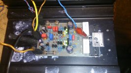
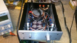
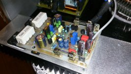
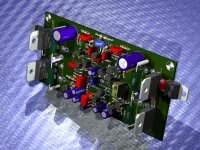
Small update, I have managed to stuff the enclosure with amp boards (two different versions Left and Right). Now i will have to make a listening test to make sure that all is OK.
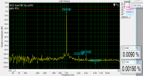
DF was measured on finished amp after protect relay and inductor coil. I have seted the gain at x47 cause I am not going to use any preamp. After I will listen to It for a while I will post all schematics, thermo-transfer files etc.
So far it looks like bellow.
DF was measured on finished amp after protect relay and inductor coil. I have seted the gain at x47 cause I am not going to use any preamp. After I will listen to It for a while I will post all schematics, thermo-transfer files etc.
So far it looks like bellow.
Attachments
LC
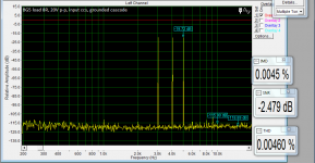
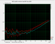
I do not know, my card is measuring properly only to 20k so I can measure 2nd harmonic only at 9-10k. But i thik is good enough to listen the music anyway.
It's not 'good enough' to listen the music it's the best
")
apexaudio
THX
This kind of amp is very neutral/natural in sound and I think not for all would be good.
I think your idea from the 1st post would be nice to try and finish in 100%. I remember first prototype with 4 LTP's and it was sounding stunning but I do not know how to resolve the clipping issu on sine wave above 5kHz, other than that it was super.
apexaudio
THX
This kind of amp is very neutral/natural in sound and I think not for all would be good.
I think your idea from the 1st post would be nice to try and finish in 100%. I remember first prototype with 4 LTP's and it was sounding stunning but I do not know how to resolve the clipping issu on sine wave above 5kHz, other than that it was super.
Yes I must finish this amp
apexaudio
THX
This kind of amp is very neutral/natural in sound and I think not for all would be good.
I think your idea from the 1st post would be nice to try and finish in 100%. I remember first prototype with 4 LTP's and it was sounding stunning but I do not know how to resolve the clipping issu on sine wave above 5kHz, other than that it was super.
Borys did you try to add 4x1N4148 on this prototype?
Attachments
It was so long time ago that I do not remember, but it should help a bit, sansui was using some diode clamps at the VAS stage as far I remember. Maybe the diode clamps at the DD stage will be more helpful ??
Your desingn with 4 LTP's is very good, low Vce transistors can be used in all LTP's.
I have had MJE340/350 at the VAS stage and they are a bit slow recovering from saturation (sticking), better transistors here would help too.
Your desingn with 4 LTP's is very good, low Vce transistors can be used in all LTP's.
I have had MJE340/350 at the VAS stage and they are a bit slow recovering from saturation (sticking), better transistors here would help too.
- Status
- This old topic is closed. If you want to reopen this topic, contact a moderator using the "Report Post" button.
- Home
- Amplifiers
- Solid State
- Diamond Differential Amplifier