JLH Updated Power Supply
Hi,
I am planning on making a 15W JLH Updated version.
I'm still thinking on how to create the PCB for the amp itself, I can't seem to find a good layout.
So, since I was tired of trying to create a layout for the amp, yesterday I tried one for the power supply.
Ok, so, first, the power supply schematic (this isn't on Geoff's site, he send it to me):
The parts layout (96dpi):
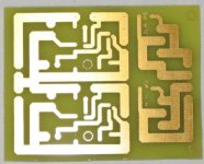
The traces (96dpi):
Both (96dpi):
Would this work, or will I encounter problems?
Any traces that should be rerouted?
Hi,
I am planning on making a 15W JLH Updated version.
I'm still thinking on how to create the PCB for the amp itself, I can't seem to find a good layout.
So, since I was tired of trying to create a layout for the amp, yesterday I tried one for the power supply.
Ok, so, first, the power supply schematic (this isn't on Geoff's site, he send it to me):
An externally hosted image should be here but it was not working when we last tested it.
The parts layout (96dpi):
An externally hosted image should be here but it was not working when we last tested it.
The traces (96dpi):
An externally hosted image should be here but it was not working when we last tested it.
Both (96dpi):
An externally hosted image should be here but it was not working when we last tested it.
Would this work, or will I encounter problems?
Any traces that should be rerouted?
have you built the amp yet? you may or may not have any problems with a conventional ps. if so, why go through all the trouble? I built one recently, powered by a very simple ps (just two 3300uf filter caps), and i have no problem whatsoever.
maybe a simple cap multiplier will do for you as well.
maybe a simple cap multiplier will do for you as well.
Good idea to start a separate thread.
Geoff has reported that the power supply makes a big difference, and others (e.g. Rod Elliott) seem to feel that a Class-A amp needs a very quiet power supply. Makes sense. Geoff has also reported that the TL431 reference is much quieter than a zener, although he also suggested a simple constant current source / resistor combination is even better.
I suggested in the other thread that you build up a prototype first so as not to get surprised. Another thing that occurs to me is that the diodes might get hot, carrying a continuous load of several amps, so check that out.
Ok, thanks for the info.
I'm going to build this circuit anyway, since I already have all the things I need for it. And it's cheaper than putting +- 8 big caps in parallel.
So the PCB layout should be fine, right?
I'm going to make some minor changes to it and then I'll make it this afternoon. (To bad my 0.8mm drill bit is broken 🙁).
I haven't made the amp itself yet, it's the first amp I'll be making. I'm still looking for a relatively cheap source for good heatsinks.
Oh, btw, I have two types of diodes. The first one are MUR410 (http://www.onsemi.com/pub/Collateral/MUR420-D.PDF) ultra fast 4A 50-600V. The second are MR856 (http://www.onsemi.com/pub/Collateral/MR850-D.PDF) fast recovery 3A 50-600V. The first one are the best, right?
Since you don't have an amp yet, you need some way to test this. Have you got a dummy load of some kind?
Not really. I've been bussy with electronics as a hobby for a year and a half now, but only recently I started getting really interested. So except for some basic tools, I don't really have anything.
How would you test this? Could I use some simple 11 ohm 5W resistors? (So that I'd get 2 amp max @ 22v)
How would you test this? Could I use some simple 11 ohm 5W resistors? (So that I'd get 2 amp max @ 22v)
Devil_H@ck said:
How would you test this? Could I use some simple 11 ohm 5W resistors? (So that I'd get 2 amp max @ 22v)
No they would smoke, 2 amp max @ 22v=44watts.
Test at first with 100 ohm 5W, then you'll need something much bigger.
🙂 sreten.
Hm, ok. Well, I'm quite certain the power supply will work. Then again, even if I want to test it I can't anyway, since I haven't got the transformer yet 🙂.
Ok, I test fitted my parts on a printed version of the PCB and noticed some flaws. If you should be interested, here's the improved PCB. It's 96 dpi.
Ok, I test fitted my parts on a printed version of the PCB and noticed some flaws. If you should be interested, here's the improved PCB. It's 96 dpi.
Attachments
use car-light bulbs for load
Hi,
pcb for a regulated powersupply is available on my site amp
amp site .
although it assumes a bridge and main caps are somewhere else.
A decent load to test a PSU can be made out of car-head-light bulbs.
They are usually 12V 50W so two in series makes a bright 24V 50W load.
Hi,
pcb for a regulated powersupply is available on my site amp
amp site .
although it assumes a bridge and main caps are somewhere else.
A decent load to test a PSU can be made out of car-head-light bulbs.
They are usually 12V 50W so two in series makes a bright 24V 50W load.
Re: use car-light bulbs for load
The PCB I am designing is for another circuit. Take a look at the first post 🙂.dutch diy said:pcb for a regulated powersupply is available on my site amp
Thanks for the tip!dutch diy said:A decent load to test a PSU can be made out of car-head-light bulbs.
They are usually 12V 50W so two in series makes a bright 24V 50W load.
Ok, everything's looking good on the PCB, I guess I'll make it today. I only need to put the screws a little bit farther from the 2 MJ15003's.
Oh, I was wondering. How do I connect something to the collector of the MJ15003? There's no pin for it, it's just the case. Do I need some kind of bar to stick trough the PCB and solder it to the underside & the case?
Or am I totally wrong asuming that these MJ15003's don't need cooling in this case?
Attachments
Or am I totally wrong asuming that these MJ15003's don't need cooling in this case?
Yes you are😉
These BJTs pass the whole current delivered to the amp, so they must be heatsinked.
Cheers
Andrea
Hi Devil_H@ck,
You can get solder tags that have an eye for a 3mm screw. Use two nuts, one to mount the transistor and the second to sandwich the tag. Then solder your wire to the tag.
Good luck and nice pcb BTW🙂
Oh, I was wondering. How do I connect something to the collector of the MJ15003? There's no pin for it, it's just the case. Do I need some kind of bar to stick trough the PCB and solder it to the underside & the case?
You can get solder tags that have an eye for a 3mm screw. Use two nuts, one to mount the transistor and the second to sandwich the tag. Then solder your wire to the tag.
Good luck and nice pcb BTW🙂
To reply your question - one of the mounting screws for a TO3 pack should make contact with the case of the semiconductor BUT NOT the heatsink. An eyelet passing through this screw can be used on the track side of the PCB to complete the electrical connection. The transistor itself should be isolated electrically from the heatsink. Check the photographs of various projects in this forum to get an idea.
Luke said:You can get solder tags that have an eye for a 3mm screw. Use two nuts, one to mount the transistor and the second to sandwich the tag. Then solder your wire to the tag.
Good luck and nice pcb BTW🙂
Thanks for the tips!Samuel Jayaraj said:To reply your question - one of the mounting screws for a TO3 pack should make contact with the case of the semiconductor BUT NOT the heatsink. An eyelet passing through this screw can be used on the track side of the PCB to complete the electrical connection. The transistor itself should be isolated electrically from the heatsink. Check the photographs of various projects in this forum to get an idea.
Typical 🙄. I can't find my cutting disks, great... That, and both my 0.8mm are broken. Oh well, I'll buy some tomorrow 🙁.
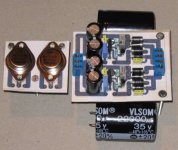
Wohoo!
Great! Guess what I found behind a pile of women's magazines 😀. Cutting discs!
This is the best PCB I've ever made (ok, it's only the 3rd I did, so what 😉). Even the sides are straight, well, except for the two I had to cut with the dremel 😉. You can even read the tiny words I put on it: "AVH '03" (= Anthony Van Herrewege 2003) and "JLH PS" (= JLH Power Supply). Well, my name is not that readable, but that's because that part of the PCB was between 2 UV lamps and the part with the "JLH PS" was right above one.
Here's the PCB:
Attachments
Re: Wohoo!
what do you have those magazines for? 🙂
Nice PCB. How do those cutting discs work?
Devil_H@ck said:Great! Guess what I found behind a pile of women's magazines 😀.
what do you have those magazines for? 🙂
Devil_H@ck said:Cutting discs!
Here's the PCB:
Nice PCB. How do those cutting discs work?
TO-3 insulation
Of the shelf "isolation-sets for TO-3" contain pads, nuts & bolts soldering-eye and plastic washers to securly tighten your TO-3 to the case and leaving a soldering eye to connect from the bottom to the housing of the device.
Devil_H@ck said:Oh, I was wondering. How do I connect something to the collector of the MJ15003? There's no pin for it, it's just the case. Do I need some kind of bar to stick trough the PCB and solder it to the underside & the case?
Of the shelf "isolation-sets for TO-3" contain pads, nuts & bolts soldering-eye and plastic washers to securly tighten your TO-3 to the case and leaving a soldering eye to connect from the bottom to the housing of the device.
- Status
- Not open for further replies.
- Home
- Amplifiers
- Solid State
- JLH Updated version in progress