Hi,
one thing: when testing the PSU check the temperature of the diodes, as I see there is no additional cooling.
On my first JLH amp I used a 50A bridge-rectifier and that needed some cooling (I screwed that to the bottom of the amp-housing)
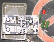
On my second JLH-amp I built the rectifier from RURG3060's and mounted
those on a alu U profile:
At full load this warms up nice.
I'm not quite sure the 3A / 4A diodes will survive the inrush current when the amp is switched on.
one thing: when testing the PSU check the temperature of the diodes, as I see there is no additional cooling.
On my first JLH amp I used a 50A bridge-rectifier and that needed some cooling (I screwed that to the bottom of the amp-housing)
On my second JLH-amp I built the rectifier from RURG3060's and mounted
those on a alu U profile:
An externally hosted image should be here but it was not working when we last tested it.
At full load this warms up nice.
I'm not quite sure the 3A / 4A diodes will survive the inrush current when the amp is switched on.
Re: Re: Wohoo!
") .
.
Those were not minemillwood said:what do you have those magazines for?
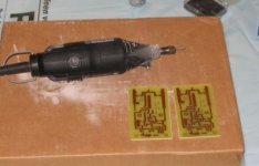
.Thanks! They are cutting discs for the dremel. Just put them on the dremel, mark the size of the PCB and cut a piece out of the standard PCB you buy in a store.millwood said:Nice PCB. How do those cutting discs work?
I plan on glueing a DIP heatsink on the diodes with special cooling paste/glue. A DIP16 heatsink should fit nicely.dutch diy said:one thing: when testing the PSU check the temperature of the diodes, as I see there is no additional cooling.
Geoff told me that too. I guess I'll have to look for other diodes then.dutch diy said:I'm not quite sure the 3A / 4A diodes will survive the inrush current when the amp is switched on.
PSU Voltage
Hi!
May be here is the right place for this question:
What is the max PSU voltage for the JLH 1996 version?
I have a nice 300VA 2X24 V Hipersil transformator and I would like to use for the JLH updated amp, in a non-regulated PSU, but I don't know the 30V isn't too high?
(Somewhere I read that 60 V is the max and 40 V is the optimum for the 1969 version.)
Thanks
I wouldn't worry too much about in-rush currents: those diodes are surprisingly resilent, . I am using GBU8 bridge for my products. Those are rated at 8amp continues, but can take 200amp rush current.
unless you are using some huge capacitors, I wouldn't worry too much about the diodes.
. I am using GBU8 bridge for my products. Those are rated at 8amp continues, but can take 200amp rush current.unless you are using some huge capacitors, I wouldn't worry too much about the diodes.
Devil_H@ck said:Are 22 000µF caps considered huge? Now I only have to find a heatsink for them, since my supplier didn't have DIP16 sinks.
I did a quick simulation. assuming a 22v peak transformer, a 22000uf cap with 40mohm esr, half wave rectification (for simplicity). the inrush current is about 120a, and charging current about 30amp (should be 15amp if you use a bridge).
it sounds like pushing the limit on the inrush current for a 4amp diode.
as to heatsinks, i am not sure if you need one. I ran my gbu8k at 5amp for extended period of time, without any heatsink. it feels just "warm" (like slightly above the temperature of my hand).
so try it without heatsink first and see if that works.
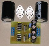
Well, I don't really know why I used discrete diodes . Probably because they don't look at like a bridge rectifier on the schematic (eg. not in the typical square form). And I happened to come across some ultra fast diodes. I guess that's why .
The max inrush current for the diodes is 125A actually, so that is indeed close to the limit. Well, I guess only time and experience will tell.
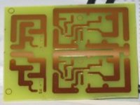
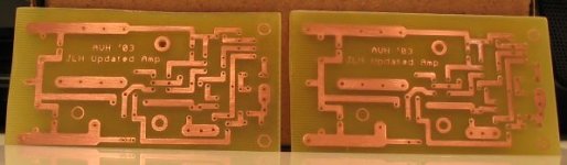
Btw, I just made the 2nd PCB board. Except for the fact that I cut this one even more 'not-straight', it came out very well. The discovery of a microwave to warm up the etching substance sure is nice.
Here's the 2nd PCB, not that it's that exciting, but I have to test the newly acquired Canon PowerShot A70, don't I?
. Probably because they don't look at like a bridge rectifier on the schematic (eg. not in the typical square form). And I happened to come across some ultra fast diodes. I guess that's why .The max inrush current for the diodes is 125A actually, so that is indeed close to the limit. Well, I guess only time and experience will tell
.Btw, I just made the 2nd PCB board. Except for the fact that I cut this one even more 'not-straight', it came out very well. The discovery of a microwave to warm up the etching substance sure is nice
.Here's the 2nd PCB, not that it's that exciting, but I have to test the newly acquired Canon PowerShot A70, don't I
?Attachments
Cool, just asking. I'll stick with my bridges then
My friend made all his own PCBs for his senior project. He was able to mount some pretty small surface mount components too. Pretty amazing for a laser printer and a Kinkos copier.
But anyway, he told me the same thing, heat up the water and it works faster, but watch out. He heated it up too much that as soon as he dropped it in the etching solution it etched away all his traces too.
--
Danny
Lolazira said:But anyway, he told me the same thing, heat up the water and it works faster, but watch out. He heated it up too much that as soon as he dropped it in the etching solution it etched away all his traces too.
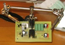
. That must have been very hot . I think it also depends on the kind of etching solution you're using.Anyway, I just finished drilling the holes. Too bad I only have a 0.8mm & a 1mm drill. The diodes leads are +- 1.25mm thick, so it's a pain to make those holes bigger. Now, I just have to wait for the flux protector spray to cure on the PCB.
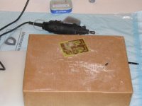
Here's a shot of my professional drill setup
. I was halfway making the diode holes bigger.Attachments
JLH Updated PCB Design
* I didn't post this in the 10W JLH thread, because it's just a PCB layout and it really hasn't got that much to do with developping the JLH further.
I made a PCB design for the JLH Updated version, including C4.
Would this be a good layout/design?
The potmeters are overlapping because the ones in Eagle's library have pins more to the side, while the one I bought have pins in the middle. This is not a fault.
All the traces to the collectors & emitters of the MJ15003's are 150 mils wide. The traces to the output + & - are also 150 mils wide, as are the traces from V+ & V-.
The red line is a trace I haven't made yet, but I don't have to, since the 2 solder pads to both sides of it are for a jumper wire.
Would this work? The image is 184dpi, not that it really matters.
* I didn't post this in the 10W JLH thread, because it's just a PCB layout and it really hasn't got that much to do with developping the JLH further.
I made a PCB design for the JLH Updated version, including C4.
Would this be a good layout/design?
The potmeters are overlapping because the ones in Eagle's library have pins more to the side, while the one I bought have pins in the middle. This is not a fault
.All the traces to the collectors & emitters of the MJ15003's are 150 mils wide. The traces to the output + & - are also 150 mils wide, as are the traces from V+ & V-.
The red line is a trace I haven't made yet, but I don't have to, since the 2 solder pads to both sides of it are for a jumper wire.
Would this work? The image is 184dpi, not that it really matters.
Attachments
Merging threads
Dear moderators, would it be possible to merge this thread with this one http://diyaudio.com/forums/showthread.php?s=&threadid=24320 and change the title to "JLH Updated version in progress" or something?
Thanks!
Dear moderators, would it be possible to merge this thread with this one http://diyaudio.com/forums/showthread.php?s=&threadid=24320 and change the title to "JLH Updated version in progress" or something?
Thanks!
i think on Not Just Another Aleph thread you can see Peter soldering
right on to the case of a TO3... pretty cool
see picture here
right on to the case of a TO3... pretty cool
see picture here
I don't think it's really necessary to start a new thread for my question, so here it goes.
I was browsing on the Reichelt Elektronik site for some parts my local store doesn't have and I came across some loudspeaker connectors.
Would this be a good choice for:
A. Loudspeaker connection:
- chassis part: Click me
- cable part: Click me
B. Signal input:
- chassis part: Click me
Are these good choices or should other types of connections be used?
your JLH Amp
Hi
I am happy to see you have found a heatsink for the amp but you will need 2 of threes per moneblock to be safe it will get hot as In burn fingers the trans may well fail if this happens you will take out your speakers mount one mj15003 amp & the other PSU mj 15003 on one heatsink sane on other side for one amp pleas be be aware that setting the current on the presets if you switch on the amp if this is to height you will nuk the output trans on switch on send your web site link to Geoff I am sure he will help you as to you’re sockets yes you can use these but I would use the normal binding posts gold plated
Ps
when you have finished you amp how would you like to make a PCB for the JLH Headphone amp
Colin
- Status
- This old topic is closed. If you want to reopen this topic, contact a moderator using the "Report Post" button.
- Home
- Amplifiers
- Solid State
- JLH Updated version in progress