I ordered 2 since you never know what can happen
Ciao!
Do
I'd hoped you ordered more than one
We have sent to all who have paid before 9pm gmt+1 yesterday.
9 packages today. Expect 2 - 5 days.
Best regards
Sonny and Miriam Andersen
Sonny, Miriam,
Package arrived this morning. That's very fast!
Had given up trying to source E rated parts until your kind offer.

Thank you!!
Paul
We have sent to all who have paid before 9pm gmt+1 yesterday.
9 packages today. Expect 2 - 5 days.
Best regards
Sonny and Miriam Andersen
Package arrived today
Let us know if they do not arrive with a week. If so we will send a new package. It will always be a gamble to send it as ordinary post.No mail here. Martin Luther King Jr day today.
But if it should be send as a package they would be way to expensive.
Whatever the music is played the NX amp sounds good in my system...
Fab
Whatever the music is played the NX amp sounds good in my system...
Fab
Complex music at high levels too? unlike Junie's experience.
Complex music at high levels too? unlike Junie's experience.
I can confirm this as well. Fab brought his nx Amp at my place and we hooked it up on my audio gears and I can attest that it sounds superbly good at all levels. Image depth is just stunning on this amp!
I'm also finishing up my build
Ciao!
Do
I can confirm this as well. Fab brought his nx Amp at my place and we hooked it up on my audio gears and I can attest that it sounds superbly good at all levels. Image depth is just stunning on this amp!
I'm also finishing up my build
Ciao!
Do
Thanks for the review. It gives me confidence with going ahead with the build which I had briefly shelved.
Complex music at high levels too? unlike Junie's experience.
Possibly the power supply...?
I have a power supply dual mono with 300va transformer per channel with CRC of 10000uf - 0.1 ohm - 20000uf per polarity/per channel. Also, I set the bias a little higher than original with lower emitter resistors value on the output stage. My power supply voltage is +/- 42vdc.
Fab
Last edited:
Possibly the power supply...?
I have a power supply dual mono with 300va transformer per channel with CRC of 10000uf - 0.1 ohm - 20000uf per polarity/per channel. Also, I set the bias a little higher than original with lower emitter resistors value on the output stage. My power supply voltage is +/- 42vdc.
Fab
Yes, a stiffer PSU is almost always sonically better, especially when the output stage is designed to deliver more current. When the output stage is current restricted rather than voltage, making the supply sag a bit helps with both amp stability and sonics. LM3886 is a typical example, although chip based.
Another big Cap across +- rails may help a little more with sonics. Keep up the good work, Bonsai and Fab.
Sam,
Why would you want the power supply to sag on the chip amp? Wouldn't a limit to the upper voltage but a stiff rail work just as well in that case?
What you say is also true, but I guess because you clip the amp much earlier being voltage restricted, the dynamics suffer. If you look at some of the build threads of the LM3886, like Peter Daniel's for example, you will find that 1000uF per rail fitted close to the chip gave the best results.
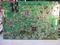
OK, so I'm all ready to start soldering my parts and figure I'll start with the SMD parts. First one I grab is BZX585. D17. Can't for the life of me find it on the PCB. OK, I set that aside, and grab BAS21H. D2 & D6. Great, I find them on the PCB get ready to solder them and it dawns on me I don't have a clue which end goes which. Seems the polarity is not marked by the silk screen. Guess I need some help determining the orientation. Someone who is familiar with SMD please help me out.
Thanks, Terry
Thanks, Terry
Terry,
Assembling using SS alone, is not a very good idea, unless it is very well done, which it does not sound like in your case.
Assembly drawing/BOM are the references to follow. In many dense designs, 0603/0402, it is hard to see comp's using SS.
Do you have a 10x magnifier?, I use both a jewelers loup and have one of those headbands as well.
It is almost imperative to have magnification for SMT, regardless of type.
Also good light, as at times you have to view comp markings on a angle to get the right contrast. Many comps are laser marked/etched, so it is difficult to see, unless you have the light/angles just right.
Good tweezers, no-clean glow core solder, two irons with fine chisel tips, are the ticket. I have done SMT since the 80's.
Mouser Part #: 38-13368
Manufacturer Part #:13368
Manufacturer:AIM
Description:Solder Sn63/Pb37 GLOWCORE2% .015 DIA 1/2 lb.
BAS21H diode will have a line to mark cathode.
If in doubt, always check mfg DS, they will show markings, even give the code, which is 2-3 digit code, ie "3A5" to confirm it is exactly what it should be = more 10x mag, see my point ?
I always do the passives first, starting with C's, R's. Gets you warmed up for the fine pitch stuff.
THT stuff at the very end.
Sometimes, I will assemble partially, like PS, get it going/test then continue.
Place very small bit of solder on one pad, place comp, using tweezers, re-heat joint and get comp aligned and flat, do the other terminal, go back and add a touch more solder on the fist pad so that you get a nice fillet. Inspect, use 50mil solder wick if you have too much solder. You aim for a nice glossy joint, with a fillet and no icicles.
Attachments
Last edited:
Thanks for the tips. Fortunately I had just bought a magnifying lamp yesterday so I had that covered. My main problem was not knowing how to tell the orientation for the diodes as there are no markings on the PCB. I thought I was missing something. I finally just used the schematic and followed the traces on the PCB to determine the orientation. I had watched a few videos on youtube about soldering SMDs so I had a bit of an idea what was in store. Not a fan right now. I spent more time getting those few parts soldered than it usually takes to solder up a whole board of through hole. Learned something new so it's OK.
Blessings, Terry
Blessings, Terry
- Home
- Amplifiers
- Solid State
- SX-Amp and NX-Amp