Hi everyone,
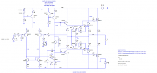
I'm thinking about using this circuit to protect the output of the amplifier that I'm projecting, but I don't know if this is a good circuit, it was told me that this circuit could bootstrapp the output at high frequencies is this true?
What's the purpose of the two capacitors?
Does anyone tested this protection system?
Thank you very much for your attention,
Best regards,
Daniel Almeida
Attachments
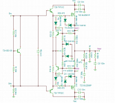
Which 2 capacitors are you referring to? If it is to pairs C8/9 or C10/11, there is a film capacitor intended to improve the HF performance of the electrolytic which acts as local supply bypassing (aka decoupling). At these values with good quality electrolytics, it seems misguided in the light of a little analysis but when the book was written, it was probably still common practice. 'Trust that's what you meant.
First I don't think it's a "multislope limiter"; I suspect it's merely a single slope single breakpoint limiter. Secondly, because it is refered to ground, the position of the protection locus would vary with changes in the supply rails.
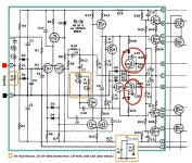
If you mean the capacitors across the base collector junctions of the protection transistors, these are meant to prevent limiter activation at HF, but are misconceived because in this position they actually increase distortion. This is because they shunt the output stage out of the feedback loop at HF; far better to place them across the base emitter junctions of the limiter transistors.
Read that paper I sent you on VI limiters.
That protection circuit is good but there's a problem with your implementation.
The way it's drawn it tries to clamp the gate drive voltage when load is shorted , so far so good, but you show it connected to the driver transistors emitters, which are able to supply *a lot* of current.
Those TO220 TIP will *murder* those little 2N5xxx .
1) the clamping action will be quite undefined.
2) either the drivers or the clamping transistors or both will die.
You must clamp the driver transistors *base* and you must add a series resistor to each (typically around 470 ohms) to provide a defined impedance to work with.
As of C2 and C3 the value and position (clamping transistors base to collector) is fine, they are used because is common for the amplifier to oscillate wildly while clamped so the added caps kill HF response *while protecting* .
There is no effect on the amplifier under normal conditions of use, since they are not activated and besides, they are separated from the circuit by those 1N4148 diodes until called on duty.
I think you cut and pasted elements (or pulled ideas) from different schematics, which are not compatible with each other.
My website is down at the minute. When it's back up, I will post your paper up Michael.
Ok.
As of C2 and C3 the value and position (clamping transistors base to collector) is fine.....
No.

Well, you are entitled to your own opinion.
Pity Pro designers don't share it

Just a few examples (out of tens of thousands) of real world amps (not "simulations") who *do* use BC caps in the protection transistors.
Would you trust Dynaco 400?
AmpegB3/VH140/SVT200?
Dynaco ST?
Crate 1200?
Gibson Lab Series?
Peavey Commercial PA amplifiers?
What do they all have in common?
*All* are high power amps, meant for grueling PA/stage/live sound, driving long cables, funky impedance speakers, high probability of shorts, continuous abuse; no cork sniffing designs survive or perform there.
Attachments
-
 Peavey CS400.gif22.5 KB · Views: 147
 -
 Lab_Series_L5_L7_L9_L11_scheme.gif87.6 KB · Views: 131
 -
 Crate1200H.gif39.2 KB · Views: 140
 -
 Dynaco-ST410sch_det.jpg113.8 KB · Views: 153
 -
 SVT200Tschem_notes.gif116 KB · Views: 247
 -
 Ampeg-VH140C-schematics_Page_8.gif138.4 KB · Views: 255
 -
 AmpegB3.gif26.4 KB · Views: 254
 -
 Dynaco400.gif115.1 KB · Views: 280
Your paper is welcome at juanmanuelfahey dot gmail dot com , and will be read with utmost respect, but beware that it will hard to twist the *FACT* of universal use by respected and very successful Manufacturers .
Well, you are showing some chutzpah !!!!
Tell Dynaco/Ampeg/Peavey/Crate/Laney/Gibson/ .... /1000 others that they have been wrong for the last 30 or 40 years.
Maybe they should recall their production?
??????????????And every single example you've shown is a poor design in almost all respects.
Well, you are showing some chutzpah !!!!
Tell Dynaco/Ampeg/Peavey/Crate/Laney/Gibson/ .... /1000 others that they have been wrong for the last 30 or 40 years.
Maybe they should recall their production?
Tell Dynaco/Ampeg/Peavey/Crate/Laney/Gibson/ .... /1000 others that they have been wrong for the last 30 or 40 years.
Maybe they should recall their production?
I could teach them a thing or two.
Hi everyone,
I'm thinking about using this circuit that is included in Michael Kiwanuka's papers on SOA protection, because it seems simple and effective, I think that the base resistors are two high maybe I should try a lower value.
Best regards,
Daniel Almeida
I'm thinking about using this circuit that is included in Michael Kiwanuka's papers on SOA protection, because it seems simple and effective, I think that the base resistors are two high maybe I should try a lower value.
Best regards,
Daniel Almeida
Attachments
I could teach them a thing or two.
Tell them so
They will hire you as a consultant for a 5 figure salary
Although people who have successfully built hundreds of thousands of amplifiers "the wrong way" and are the Industry Leaders, probably won't be much impressed by a green Engineer who points a finger at them and calls them fools.
I have used multi slope VI limiting (on my Ovation 250 design). I also used a low value cap base to collector, but this was primarily because when the VI limiting was activated, the amp oscillated at HF which is to be expected. I have seen designs (some examples above) where a base emitter cap is used with the notion of of shaping the time response of the limiter.
I have used multi slope VI limiting (on my Ovation 250 design). I also used a low value cap base to collector, but this was primarily because when the VI limiting was activated, the amp oscillated at HF which is to be expected. I have seen designs (some examples above) where a base emitter cap is used with the notion of of shaping the time response of the limiter.
That's the point.
By the way, that's an oscillation which never comes out in simulation, but often in a real world amplifier.
Hi Michael,
I've been reading your paper and I'm interested in a solution based on the circuit of figure 28 (dual slope single breakpoint non-linear foldback limiter), but I don't understand the formulas I should use to calculate the resistors and the zener diode voltage. I need a protection against short to ground, and protection against very low loads (< 3 ohm).
Best regards,
Daniel Almeida
Danny,
do you need a limiter that prevents excessive dissipation in the output devices and/or excessive dissipation in the driver devices?
Should the limiter activate when a valid audio signal is sent to the output?
Should the limiter activate when only a valid audio load is connected to the output?
Once you have answered these questions, look back at your requirements in post18 and decide whether they are really what you want or need.
BTW,
many builders refuse to fit any form of limiting and the reason they give is usually related to the presumed effect the limiter will, or might, have on the quality of the sound performance.
I think some of this is related to the trigger level of the detection transistor, where at the start of turn on of the limiting, is around 400mVbe.
Many design their limiting assuming a triggering voltage of around 600mVbe to 650mVbe.
Many design their limiting that triggers at the same value of DC current output as they do for a very short term transient current. This automatically reduces the transient capability of the amplifier to be crippled. It will affect the sound performance if the transient capability is set to the same limited current value as the "safe" DC current limit.
eg.
assume the "safe" short circuit current is 6Adc and this occurs when Vbe is 600mVbe.
That detection transistor will start to turn on at 4A. If the transient current also starts limit at 4Apk, then in my view the limiter is faulty/badly designed. The capacitors referred to earlier are an attempt to increase transient current to some value significantly above the DC limit.
Andrew:
All you said maybe the VI limiter don't need for diy, hi-fi amp.
But, they need for a design what's a amp often moving, not fixed load, like pro amp... Accepted linear distortion.
I'm interest this problem. And looking for a good circuits, protect SOA, short circuit, and easy, simple.
All you said maybe the VI limiter don't need for diy, hi-fi amp.
But, they need for a design what's a amp often moving, not fixed load, like pro amp... Accepted linear distortion.
I'm interest this problem. And looking for a good circuits, protect SOA, short circuit, and easy, simple.
- Status
- This old topic is closed. If you want to reopen this topic, contact a moderator using the "Report Post" button.
- Home
- Amplifiers
- Solid State
- Randy Slone's multislope VI limiter