By the way, that's an oscillation which never comes out in simulation, but often in a real world amplifier.
That oscillation is also visible in simulation, and it's an indicator of how the VI limiter works and is not a function of the amplifier's feedback loop misbehaving.
Hi Michael,
I've been reading your paper and I'm interested in a solution based on the circuit of figure 28 (dual slope single breakpoint non-linear foldback limiter), but I don't understand the formulas I should use to calculate the resistors and the zener diode voltage. I need a protection against short to ground, and protection against very low loads (< 3 ohm).
Best regards,
Daniel Almeida
There are no shortcuts. First you need to draw the SOA of your chosen power transistors on linear-linear graph paper (or you can do this in Excel), and then draw your derated double slope protection locus on this graph. Make sure your locus crosses the Vce axis at a Vce value greater than the sum of the supply rails.
Then you select points on you locus that you can use to calculate the corresponding component values as described in the article. You have to be able to solve a pair of simultaneous equations; get Texas Instrument's Ti-89 calculator for this; it's what I use. The value of the zener diode should be, as a rule of thumb, less than half of the value of one supply rail; ideally use a temperature compensated zener.
After you've computed all the component values you may run a simulation of the limiter in SPICE as described in the article to establish whether your values are correct, and to check the effect of changes in ambient temperature on the circuit.
Hello Michael,
I'm using two paralleled output MOSFETS in complementary (push-pull) topology, I wanted to make this amplifier with +/- 45 V supply rails and a minimum load of 4 ohm, I don't know if it's better to use 3 output pairs thought, because I know that the impedance can be 2 ohm or less at lower frequencies for a 4 ohm rated speaker.
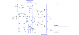
I've attached the datasheets of the output devices, the amplifier design I'm projecting (Bob Cordell based), and the models used.
I've never made a SOA graph, can you help me here?
Normally I setup two points where current limiting is needed, for a load inferior to 2 ohm, and near short-circuit and then making the calculations based on Idmax and Pdmax.
I also have the TI89 Titanium from Texas Instruments it's very useful in the electronics and telecomunications BSc degree I'm taking.
Thank you very much for your attention,
Best regards,
Daniel Almeida
I'm using two paralleled output MOSFETS in complementary (push-pull) topology, I wanted to make this amplifier with +/- 45 V supply rails and a minimum load of 4 ohm, I don't know if it's better to use 3 output pairs thought, because I know that the impedance can be 2 ohm or less at lower frequencies for a 4 ohm rated speaker.
I've attached the datasheets of the output devices, the amplifier design I'm projecting (Bob Cordell based), and the models used.
I've never made a SOA graph, can you help me here?
Normally I setup two points where current limiting is needed, for a load inferior to 2 ohm, and near short-circuit and then making the calculations based on Idmax and Pdmax.
I also have the TI89 Titanium from Texas Instruments it's very useful in the electronics and telecomunications BSc degree I'm taking.
Thank you very much for your attention,
Best regards,
Daniel Almeida
Attachments
I've never made a SOA graph, can you help me here?
In order to learn you have to do the work yourself. Read the paper from start to finish very carefully. Do not use MOSFETs as you have to match them for Vgs, which is a pain. Use BJTs.
I don't have BJTs, I have to buy them, but I have lots of MOSFETs. MOSFETs don't have second breakdown, can you help me, please.
I've never made a SOA chart and I can't understand how do you do it in your paper.

PS:
The MOSFETs are the output devices, not the protection devices.
Thank you very much for your attention,
Best regards,
Daniel Almeida
I've never made a SOA chart and I can't understand how do you do it in your paper.
PS:
The MOSFETs are the output devices, not the protection devices.
Thank you very much for your attention,
Best regards,
Daniel Almeida
Last edited:
I've never made a SOA chart and I can't understand how do you do it in your paper.
Buy a book of linear-linear graph paper. Now, if you have, say, a 200W transistor, you draw the collector current on the y-axis and the Vce on the x-axis.
You simply divide 200 by an arbitrarily selected collector current to obtain the corresponding Vce. You do this for several points untill you have enough to draw the power curve.
For a MOSFET you do not need to draw the secondary breakdown curve as it doesn't exist. For BJTs the points to plot the secondary breakdown curve can be obtained from the log-log SOA curve given in their data sheet.
Thank you Michael,
I'll try to do that, I can use your circuit of figure 28 to protect my MOSFET output, right?
In the linear-linear paper I've to draw a graph with Id(Vds), to obtain the Vds, I can obtain the drain source voltage with Vds = Pdmax/Id, and after having some points i can connect them and then I get the curve, right.
Best regards,
Daniel Almeida
Correct.Thank you Michael,
I'll try to do that, I can use your circuit of figure 28 to protect my MOSFET output, right?
In the linear-linear paper I've to draw a graph with Id(Vds), to obtain the Vds, I can obtain the drain source voltage with Vds = Pdmax/Id, and after having some points i can connect them and then I get the curve, right.
Best regards,
Daniel Almeida
Some say that FET outputs don't need protection. Presumably because the SOAR does not drop significantly at high Vds.
All power semiconductors need protection.
Some say that FET outputs don't need protection. Presumably because the SOAR does not drop significantly at high Vds.
All power semiconductors need protection.
Agree and add: although having much better SOAR definitely helps, they still must dissipate heat.
If you have a MOSFET self limiting to, say, 7A and with 50V rails, it's still dissipating 7A * 50V * 0.5= 175W of heat.
It *will* stand that for a few seconds, *maybe* allowing a fuse to blow, *maybe* long enough for a bimetallic thermal switch attached to the heatsink to open , but ... why play Russian Roulette?
A good VI protector will allow it to survive better any day of the week and so is worth using.
Here in post #78 is where AndrewT posted the article pages .if you do a search for David Eather you will find it.
It used to turn up readily but that magazine changed the way the libraries work and it takes a bit of persistence to get it to show up.
http://www.diyaudio.com/forums/solid-state/158520-output-transistor-safe-operating-area-8.html.
A bit more digging and we find clearer PDFs in appendix 4 on this web page
Thank you Michael and all diyers for your support,
I don't have an heatsink yet, because this amplifier is stereo (I will replicate the design for both channels) and I need an enormous heatsink and that's difficult to find in my country, I've to order one from RS, another question, it's a good ideia to use forced ventilation?
How I should set the protection locus?
About your question, yes I'm using BUZ900/905 pair, which are medium/low power MOSFETs.
I've this pdf about heatsink dimensioning that I've got from ST, I could use this formulas?
Best regards,
Daniel Almeida
Attachments
- Status
- This old topic is closed. If you want to reopen this topic, contact a moderator using the "Report Post" button.
- Home
- Amplifiers
- Solid State
- Randy Slone's multislope VI limiter