This project is aimed at those wanting to add a simple speaker switch on delay to an amplifier to eliminate the annoying and possibly speaker damaging thumps/pops/bangs that many amplifiers make when first powered up and the sometimes strange noise when powered down.
The term "universal" comes from the idea that the design can be scaled to suit most amplifier power supplies and that the delay time is adjustable.
The aims of the design can be summarised as,
1. To work with a wide range of transformer voltages.
2. The switch on delay must be repeatable and reliable and must give the "full" delay time even in the event of a brief mains interuption or cycling of the on/off switch.
3. The relay should drop out near instantly on power off.
4. Power saving is used by running the relay at reduced coil voltage yet with a high voltage "pulse" to close the relay smartly and reliably.
These points will all be explored by understanding how the circuit operates. That in turn should enable the user to be able to alter the circuit to suit their own requirements.
The circuit...
I drew the circuit in Spice more for clarity as much as anything else, however I found that it was possible to simulate it as well although the component
values used in the simulation are different from the "real world" values that the circuit works well with. This simulation problem is almost certainly
caused by the Triac model used. So on to the real circuit... understand how it works and you can modify it to suit.
(And why a triac ? To "kick" the relay with a high pull in voltage require that the device driving the relay operates quickly. A transistor "drifts" into
conduction as the base current rises which would not pull the relay in quickly enough when the relay is fed from the power saving series resistor feed)
The power supply.
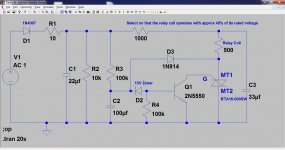
D1, C1 R1 and R2 form the PSU for the circuit. The AC feed can be taken from across one or both secondary windings depending on the voltages of the
transformer. The circuit is not ground referenced in any way.
D1. Half wave rectifier.
R1. Can be added if desired. A small 0.5 watt resistor both acts as a safety feature (consider it a fuse) and also might make life a little easier for C1.
R2. Helps discharge C1 when power is removed.
C1. Is the "reservoir" cap. The small value ensures a rapid drop out of the relay on power off. This cap should be of good quality, possible a slightly larger 100 volt component as these have a more generous ripple current rating.
The timing components.
R3 and C2. These are the "timing components". R3 has to be "low enough" to supply sufficient base current to Q1. So to alter the delay C2 value can be
varied.
The trigger circuit.
D2, R4 and Q1
D2, the zener ensures that no base current flows until the voltage across the timing cap has reached the zener voltage plus vbe of Q1. R4 ties the base of
Q1 to ground to ensure it never "floats" when the zener is non conducting. Q1 conducts when base current flows. Q1 should be a reasonably high gain device.
The Triac.
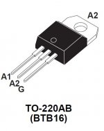
The triac is a BTA16-600SW device. This is a "sensitive" gate trigger type (easily triggered) and has a low "minimum holding current". Triacs are
interesting devices and can be triggered in one of four "quadrants" depending on the polarity of the voltage across the main terminals. Once triggered the device remains conducting and can only be turned off by interupting the current flowing between the main terminals.
(Refer to the pinouts of the triac in the data sheet AND NOT the LTspice symbol which to me is back to front)
MT1 connects to the relay.
MT2 connects to ground.
The triac is triggered by pulling the gate to ground. This is done by trigger Q1 as explained earlier.
The remaining components.
The relay coil is fed via a series resistor. You will have to determine the value of this depending on the relay. Get this value correct and the relay will
run on a much lower coil voltage than its rating saving power and producing less heating in the relay. My relay was a 12 volt 500 ohm device. There is nothing to stop you running two relay coils in series or parallel depending on what suits best. The triac seemed happy with holding currents below 10 ma.
C3. This "kicks" the relay with the full supply when it activates and ensure a smart and rapid pull in. The value can be up to a 100uf if the supply
voltage is low. Even a 22uf works well on the higher supply voltages.
D3. The clever bit. When the triac triggers the voltage on MT1 falls to near zero. We can use this to pull the voltage on the timing cap to near zero via the diode. This ensures that the timing cap is ready to "start again" should there be a brief mains interuption or quick operation of the on/off
switch. The diode also serves as a snubber network across the triac in series with C2.
Real world components values.
470K and 47uf works well for the timing components R3 and C2. These give around an 8 second delay.
For 18 Vac input the zener should be around 6.2 volts.
For 36 Vac input a 15 volt zener is better.
R4 is 560K
Select the series feed to the relay to suit.
The pictures.
1. The circuit diagram (but refer to text for values)
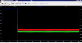
2. The timeline of operation showing the delay, the voltage across the triac and relay and the relay current.
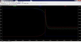
3. A close up of the transition period.
4. The relay "kick" current.
5. The triac pin outs. A1 and A2 are "main anode" which equate to MT1 and MT2 (main terminals).
Finally the zipped folder contains the simulation files which will run in LTspice.
The term "universal" comes from the idea that the design can be scaled to suit most amplifier power supplies and that the delay time is adjustable.
The aims of the design can be summarised as,
1. To work with a wide range of transformer voltages.
2. The switch on delay must be repeatable and reliable and must give the "full" delay time even in the event of a brief mains interuption or cycling of the on/off switch.
3. The relay should drop out near instantly on power off.
4. Power saving is used by running the relay at reduced coil voltage yet with a high voltage "pulse" to close the relay smartly and reliably.
These points will all be explored by understanding how the circuit operates. That in turn should enable the user to be able to alter the circuit to suit their own requirements.
The circuit...
I drew the circuit in Spice more for clarity as much as anything else, however I found that it was possible to simulate it as well although the component
values used in the simulation are different from the "real world" values that the circuit works well with. This simulation problem is almost certainly
caused by the Triac model used. So on to the real circuit... understand how it works and you can modify it to suit.
(And why a triac ? To "kick" the relay with a high pull in voltage require that the device driving the relay operates quickly. A transistor "drifts" into
conduction as the base current rises which would not pull the relay in quickly enough when the relay is fed from the power saving series resistor feed)
The power supply.
D1, C1 R1 and R2 form the PSU for the circuit. The AC feed can be taken from across one or both secondary windings depending on the voltages of the
transformer. The circuit is not ground referenced in any way.
D1. Half wave rectifier.
R1. Can be added if desired. A small 0.5 watt resistor both acts as a safety feature (consider it a fuse) and also might make life a little easier for C1.
R2. Helps discharge C1 when power is removed.
C1. Is the "reservoir" cap. The small value ensures a rapid drop out of the relay on power off. This cap should be of good quality, possible a slightly larger 100 volt component as these have a more generous ripple current rating.
The timing components.
R3 and C2. These are the "timing components". R3 has to be "low enough" to supply sufficient base current to Q1. So to alter the delay C2 value can be
varied.
The trigger circuit.
D2, R4 and Q1
D2, the zener ensures that no base current flows until the voltage across the timing cap has reached the zener voltage plus vbe of Q1. R4 ties the base of
Q1 to ground to ensure it never "floats" when the zener is non conducting. Q1 conducts when base current flows. Q1 should be a reasonably high gain device.
The Triac.
The triac is a BTA16-600SW device. This is a "sensitive" gate trigger type (easily triggered) and has a low "minimum holding current". Triacs are
interesting devices and can be triggered in one of four "quadrants" depending on the polarity of the voltage across the main terminals. Once triggered the device remains conducting and can only be turned off by interupting the current flowing between the main terminals.
(Refer to the pinouts of the triac in the data sheet AND NOT the LTspice symbol which to me is back to front)
MT1 connects to the relay.
MT2 connects to ground.
The triac is triggered by pulling the gate to ground. This is done by trigger Q1 as explained earlier.
The remaining components.
The relay coil is fed via a series resistor. You will have to determine the value of this depending on the relay. Get this value correct and the relay will
run on a much lower coil voltage than its rating saving power and producing less heating in the relay. My relay was a 12 volt 500 ohm device. There is nothing to stop you running two relay coils in series or parallel depending on what suits best. The triac seemed happy with holding currents below 10 ma.
C3. This "kicks" the relay with the full supply when it activates and ensure a smart and rapid pull in. The value can be up to a 100uf if the supply
voltage is low. Even a 22uf works well on the higher supply voltages.
D3. The clever bit. When the triac triggers the voltage on MT1 falls to near zero. We can use this to pull the voltage on the timing cap to near zero via the diode. This ensures that the timing cap is ready to "start again" should there be a brief mains interuption or quick operation of the on/off
switch. The diode also serves as a snubber network across the triac in series with C2.
Real world components values.
470K and 47uf works well for the timing components R3 and C2. These give around an 8 second delay.
For 18 Vac input the zener should be around 6.2 volts.
For 36 Vac input a 15 volt zener is better.
R4 is 560K
Select the series feed to the relay to suit.
The pictures.
1. The circuit diagram (but refer to text for values)
2. The timeline of operation showing the delay, the voltage across the triac and relay and the relay current.
3. A close up of the transition period.
4. The relay "kick" current.
5. The triac pin outs. A1 and A2 are "main anode" which equate to MT1 and MT2 (main terminals).
Finally the zipped folder contains the simulation files which will run in LTspice.
Attachments


back emf diode or diode+zener across the relay coil?
Doesn't seem necessary here. The top of the relay coil is all high impedance at DC, and "AC" coupled to the zero line via C3. So any "spike" there has a safe path and is hugely damped. The triac wouldn't be harmed with a "reverse bias" spike either because its happy with voltages of either polarity. Diode D3 via the timing cap (unintentionally but usefully) provides a path for that condition.
the field collapses as the triac is turned off..
nice one Mooly, perhaps you can add opto-isolators to short out the base emitter of Q1 in case of current overloads and/or dc voltage offsets at the speaker output terminals....
Thanks Tony. Good idea for adding an "input" to turn it off. Once the triac is conducting its only way of turning off is to interupt the current but its still easily do-able. An NPN transistor biased "normally on" such as for example with a resistor from base to the supply and fitted between MT2 and ground should work. To kill the relay the base would be taken low.
Can an SCR be used instead of the Triac?
Does an SCR hold ON if the gate signal goes OFF?
No that won't work. The SCR triggered with a positive going pulse. Both the SCR (Thyristor) and triac remain in conduction until either the current is removed or the current falls below the "holding value" for that particular device. On AC of course all those conditions happen automatically every time the AC passes through a zero crossing.
Nice and useful circuit.
Some observations about the component choices:
-D3 and Q1 will have a marginal or insufficient voltage rating, particularly for 230V mains
-A resistor in series with D3 is required, to limit the discharge current of the 100µF (charged to 15V) into the triac
-A resistor in series with the gate of the triac is not absolutely required, but highly advisable. Without it Q1 could pass into dangerous regions of the SOAR for some ms, when the current is close to 10mA, and the voltage not far from 300V in 230V systems.
A diac instead of the zener could help, by providing snap action (also with a proper limiting resistor)
It's not intended to be powered from the mains.
It's powered from any of the secondaries that happens to be "up" when the delay starts.
Mooly, Tony
I don't understand the back emf being allowed to be neglected.
It seems to me that the coil back emf will try to pulse against the two "closed routes" facing the bottom end, i.e. the signal diode and the triac. If the triac is rated at 600V of reverse voltage then diode is more likely to break down first. it only has a 75V rating. The fact that there are resistances in the back emf route does not reduce the likely hood of reverse breakdown. They will simply reduce the peak reverse current during the breakdown phase.
Is my thinking incorrect?
Last edited:
Nice and useful circuit.
Some observations about the component choices:
-D3 and Q1 will have a marginal or insufficient voltage rating, particularly for 230V mains
-A resistor in series with D3 is required, to limit the discharge current of the 100µF (charged to 15V) into the triac
-A resistor in series with the gate of the triac is not absolutely required, but highly advisable. Without it Q1 could pass into dangerous regions of the SOAR for some ms, when the current is close to 10mA, and the voltage not far from 300V in 230V systems.
A diac instead of the zener could help, by providing snap action (also with a proper limiting resistor)
Thanks Elvee.
Resistor for D3... good point, that's something I hadn't thought of and the peak current discharging a 100 uf or more could exceed D3's surge limits.
Diacs 🙂 rare beasties these days. My memories of diacs are the old BR100 and thyristor PSU's. I can't even quote you a modern diac device number... scary 😀
It's not intended to be powered from the mains.
It's powered from any of the secondaries that happens to be "up" when the delay starts.
Mooly, Tony
I don't understand the back emf being allowed to be neglected.
It seems to me that the coil back emf will try to pulse against the two "closed routes" facing the bottom end, i.e. the signal diode and the triac. If the triac is rated at 600V of reverse voltage then diode is more likely to break down first. it only has a 75V rating. The fact that there are resistances in the back emf route does not reduce the likely hood of reverse breakdown. They will simply reduce the peak reverse current during the breakdown phase.
Is my thinking incorrect?
I don't think your thinking is incorrect, its just that I don't think in practice there will be an issue. On switch off the circuit turns off "quickly" but not "that quickly" if you see what I mean.
I'll put a 100Mhz scope on it (probably tomorrow) and see if I can see anything.
That a signal diode that has a reverse current limiting resistor is a reliability issue. It may well last decades worth of power downs.
That is OK by me.
I was just confused that you and Tony were discarding the need for the diode or diode+zener that everyone else uses so flippantly.
It may be that the triac cannot be turned off that saves the semiconductors around it.
The supply simply decays to zero volts to allow the triac to switch off.
Is this last statement more correct?
The triac will turn off when the current falls below Ihold, which generally has a value comparable to It.The supply simply decays to zero volts to allow the triac to switch off.
Is this last statement more correct?
The remainder of the stored energy (I²L/2) will create a voltage spike, in practice the first half-cycle of a ringing because of the winding's capacitance.
That a signal diode that has a reverse current limiting resistor is a reliability issue. It may well last decades worth of power downs.
That is OK by me.
I was just confused that you and Tony were discarding the need for the diode or diode+zener that everyone else uses so flippantly.
It may be that the triac cannot be turned off that saves the semiconductors around it.
The supply simply decays to zero volts to allow the triac to switch off.
Is this last statement more correct?
Elvee mentioning the series resistor is a valid point. When the triac turns on it can be thought of as putting the 1N914 diode across the charged up cap. Its not an instant nano second switch on but is it quick enough to take the diode over its limits.
-----------------------------------------------------------------------------------------
So I've just looked at the data sheet for the diode,
non-repetitive peak forward current square wave; Tj = 25 °C prior to
surge; see Fig.4
t = 1 us - 4 A
t = 1 ms - 1 A
t = 1 s - 0.5
In practice and again I don't think there is an issue seeing those figures. To swap the diode for somthing like a 1N4004 would surely remove all doubt if anyone were concerned about it.
The back emf... I'll see what shows in the real circuit.
The scope test was interesting. Measuring on "top" of the relay i.e. on C3 and all is clean as expected. Measuring on the bottom end and this is the result...
On switch on "noise" occurs as the triac comes into conduction.
On switch off a high positive transient is seen. Highest amplitude I could discern during many off cycles was around 115v volts.
So this is one real issue with the design as it stands and the fix is simple. A higher voltage diode (the P.I.V. rating) should be used for D3. A common 1N4007 would be suitable.
I looked at ways of reducing the "noise" and found that adding a small cap across base and collector of Q1 worked well. Anything from 100pf to 0.47uf stopped the switch on "noise". Also observed was how this cap reduced the high voltage transient at switch off, the larger the cap the less the transient. Values around 470pf to 2200pf seem a good compromise. With 470pf the transient is around 40 volts peak and with a much slower rise time. Going too large in value slows the rate at which the voltage across the boost cap builds. There must be some conduction via the triac gate for this effect to occur, not enough to trigger the device but enough to impact on the charge time of the cap.
So to summarise up to now. I think fitting a 1N4007 or similar is sensible for D3, and adding a small cap in the 470 to 2200pf range across B and C of the transistor as a refinement.
Edit
Scope on 50 volts/div
Attachments


For a bit of fun I replaced the 500 ohm relay resistor in the simulation with a 1000mH inductor of 500 ohm resistance. How close that inductance value is to a typical relay I have no idea but the simulation now shows an 80 volt positive going spike at switch off.
The cap mentioned in the above post added between B and C of the transistor also seems to work in simulation by reducing the transient. The noise produced as the triac comes into conduction eludes simulation and doesn't show.
So here we have with a capacitor of 2200 pf and without.
The cap mentioned in the above post added between B and C of the transistor also seems to work in simulation by reducing the transient. The noise produced as the triac comes into conduction eludes simulation and doesn't show.
So here we have with a capacitor of 2200 pf and without.
Attachments


Did you attempt to compute, or at least simulate the actual current in the diode? I think you would be surprised.t = 1 us - 4 A
t = 1 ms - 1 A
t = 1 s - 0.5
In practice and again I don't think there is an issue seeing those figures. To swap the diode for somthing like a 1N4004 would surely remove all doubt if anyone were concerned about it..
Told you so 😉So this is one real issue with the design as it stands and the fix is simple. A higher voltage diode (the P.I.V. rating) should be used for D3
Using a transistor as a snubber to dissipate transients may not be the best of practices....The cap mentioned in the above post added between B and C of the transistor also seems to work in simulation by reducing the transient.
Anyway, making oscilloscope measurements on an equipment having all of its silicon on the mains side is completely off-limits.
This thread should urgently be closed, but where are the moderators? 😀
Did you attempt to compute, or at least simulate the actual current in the diode? I think you would be surprised.
Neither actually boss... I'll see if I can come up with anything useful 🙂
Using a transistor as a snubber to dissipate transients may not be the best of practices....
The cap across B and C moves it out of "transient spike" territory.
Anyway, making oscilloscope measurements on an equipment having all of its silicon on the mains side is completely off-limits.
This thread should urgently be closed, but where are the moderators? 😀
Absolutely, you just can't get staff 😀
(Just report any you see and the offending thread will be swiftly dealt with... honest... but make sure they are (offending) first 😛)
<snip>Anyway, making oscilloscope measurements on an equipment having all of its silicon on the mains side is completely off-limits.
This thread should urgently be closed, but where are the moderators? 😀
 Elvee, it's been stated in this thread that the circuit in question is not operated off of the mains, and operates off an available winding that is fully up at the time the timing delay starts.
This illustrates Elvee's point about the transient current in D3. How much 😀 It sure looks scary in simulation and its obviously a very valid point. I'm going to stick my neck on the block and say I don't believe it will approach anything like this in practice but it will still be high, possible a spike of a "few" amps. So the fix for that is a series resistor for D3. Value anything in the 47 to 100 ohm range. Go higher and the timing cap starts to take a more noticeable time to discharge meaning the rapid reset ability on power off is reduced. Its all relative though and we are talking fractions of a second for values below 1k
So the new data and circuit is as follows.
Transient spike is now 25 volts.
Peak current in D3 is now below 300 ma
Peak emitter current is below 8 ma
Timing cap voltage take around 15 ms to reset (still very quick)
So the new data and circuit is as follows.
Transient spike is now 25 volts.
Peak current in D3 is now below 300 ma
Peak emitter current is below 8 ma
Timing cap voltage take around 15 ms to reset (still very quick)
Attachments


- Home
- Amplifiers
- Solid State
- Simple Universal Speaker Delay Using A Triac