Why are you not considering the conventional back emf solution: the diode across the coil?
I prefer the diode + zener after D.Self and others told us that it allows faster opening.
Good question... my thinking was this,
To save on parts, was suppression needed in the first place as the triac doesn't even come close to any danger area.
The actual transient spike on the triac did exceed the 1N914 P.I.V. rating with some values of relay coil inductance hence the suggestion of the 1N4007. Add the small cap mentioned and even this problem disappears.
I haven't measured it using Dougs Selfs method but suspect it wouldn't achieve much here because the actual switch off time depends on the collapse of the rail and then the triac dropping out of conduction.
These two short 10 second video clips show how effective this triac circuit is. The format is .wmv (Windows Media Video) and so should play on any Windows PC. To make the video files small (short run time) the timing delay cap is reduced in value to give a short switch on delay.
Both clips show the relay and two led's.
The YELLOW one shows when the supply is present.
The GREEN one is supplied through the relay contacts and so show when the speakers would be connected.
Also turn the sound up and LISTEN to how smartly the contacts close.
In the first clip you will see the YELLOW led goes on and off. That is the supply being deliberately interupted to show how reliable the reset feature is. You always get the proper delay when power is re-applied.
In the second clip the resistor supplying the relay has been increased to 47K. This enables you to see the rapid switch on feature in isolation. The high value resistor does not allow sufficient holding current and so the relay keeps dropping out.
In the first clip the resistor was 6K8 with a 24 volt relay coil. That shows the energy saving feature in operation. The boost cap was 33uf in both cases.
YouTube
YouTube
Attachments
Why use triacs that add distortion over a relay that provides a solid connection ?
Why are ppl so afraid of using relays in the signal path ?
Hi Tekko,
I think you've misunderstood the circuit
") It is a relay driver.
It is a relay driver.You might want to look at the moc3011 http://www.fairchildsemi.com/ds/MO/MOC3010M.pdf Just for fun. It is a zero crossing turn on optoisolated triac.
This will drive a relay directly from the AC line. (Yes it is not the low voltage circuit you designed.)
The downside of your circuit is the single rectifier makes the power transformer unhappy.
It also introduces noise back into the AC line.
The upside is the use of a zener to slow charge and fast discharge the timing network.
Try looking at the "filtered DC Supply" of the unit with a spectrum analyzer and you will be surprised at how much noise actually comes from even a small transformer current draw imbalance! It also grows with time and is reduced by power on off transients.
It just depends on how fussy you want to get. I just suggest adding a bridge.
It just depends on how fussy you want to get. I just suggest adding a bridge.
Hi Simon,
I wanted to measure this for real. With the relay driver across one winding of a 15-0-15 transformer (that also supplied a bridge and two 6800uf caps) I measured around 0.2 mv pk/pk "glitch" directly across these reservoir caps when the driver was connected. There was no load on these reservoir caps. As soon as any load is added (such as the amplifier this circuit is aimed at) then the noise and ripple increases many hundred fold which swamps the 0.2 mv glitch caused by the relay load.
The 22uf pulls around 150 to 200ma current peaks from the transformer (give or take depending on the feed resistor you select for the relay) but these don't seem to impact on the main amplifier supply.
Not sure if thats what you meant
It is not the glitch. When you load a transformer with a single diode, this causes an unbalance in the current draw. This causes a slow magnetic shift in the operating point and slowly reduces the efficiency of the transformer. It is not large but can amount to a few percent if the system were to be left on for a month or so. When you switch the gear on the ac waveform is at some random voltage and this wipes away much of the residual magnetism. (But not all, it is a random process and averages out a bit.)
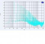
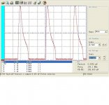
As to rectifier noise attached are a picture of the current draw and the spectrum analysis of a center tapped bridge.
All rectification causes noise. With a single diode you start at the line frequency and draw twice the current for 6 db more noise. The full wave bridge will start at twice the line frequency and with 6 db less amplitude.
Attachments
I showed this in Audioxpress. This is the tabular data showing loss with time. Note the change after a power failure.
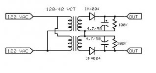
Also attached is the DC offset measurement circuit.
AC Line Out Ratio Loss % Loss
125.2 60.0 0.4792 0.0000 0.00
125.5 60.0 0.4781 0.0011 0.24
126.6 60.5 0.4779 0.0014 0.28
125.6 60.0 0.4777 0.0015 0.32
123.9 59.1 0.4770 0.0022 0.47
125.2 59.6 0.4760 0.0032 0.67
125.1 59.7 0.4772 0.0020 0.42
125.4 60.0 0.4785 0.0008 0.16
.88 VDC offset
Attachments
smart design! I like it.
As the circuit was meant for switching a speaker I'd also like to see the relay doubles a protection functionality on top of its initial intended muting@power-on purpose. Perhaps an NPN transistor or a low Rdson MOSFET can be paralleled onto the triac across A and K, when a faulty condition occurs (DC at output, over-current, etc), this transistor/MOSFET turns hard on for a very short moment bypassing the current in the triac and therefore turing it off. would this idea work?
As the circuit was meant for switching a speaker I'd also like to see the relay doubles a protection functionality on top of its initial intended muting@power-on purpose. Perhaps an NPN transistor or a low Rdson MOSFET can be paralleled onto the triac across A and K, when a faulty condition occurs (DC at output, over-current, etc), this transistor/MOSFET turns hard on for a very short moment bypassing the current in the triac and therefore turing it off. would this idea work?
smart design! I like it.
As the circuit was meant for switching a speaker I'd also like to see the relay doubles a protection functionality on top of its initial intended muting@power-on purpose. Perhaps an NPN transistor or a low Rdson MOSFET can be paralleled onto the triac across A and K, when a faulty condition occurs (DC at output, over-current, etc), this transistor/MOSFET turns hard on for a very short moment bypassing the current in the triac and therefore turing it off. would this idea work?
Thanks...
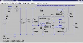
I think this would work as one option. Having a normally on device such as the NPN shown here. Pulling the base down to ground even for an instant would turn the relay off. (if the trip input trigger were a transient fault then the circuit would reset, if not then the circuit would stay tripped)
(remember that as originally intended the whole circuit doesn't need a "ground" that is referenced to the amplifiers "ground". This eneables it to be powered in a variety of ways such as "across" the transformer with no reference to the amplifiers circuits. Adding a trip input like this means that the triac circuit needs its ground line connecting to the amplifiers ground line or you could add an opto-isolator to pull the base of the NPN transistor low)
Attachments
Last edited:
- Home
- Amplifiers
- Solid State
- Simple Universal Speaker Delay Using A Triac