Hi, Im new here and Im here looking for a little help. I recently acquired some lovely vintage Toshiba 330 Hi Fi components. I have the sc-330 amp and matching tuner and pre amp. Iv been using them every day. They look and sound amazing! I have the sytem driving some lovely old Wharfdale E30 speakers.
The whole system belonged to my girlfriends dad who passed away a few years ago so they have sentimental value to her.
Yesterday was listening to some music when I the amp developed an awful static sound - something akin the sound of a Vinyl record in between songs, coming from the left channel.
I have tried removing everything that was plugged into the line in's, fiddling with all the switches on the amp and pre amp, making sure all the speaker cables are attached properly and unplugging all other electrical devices int he room all to no avail.
Also I tried headphones and the static is evident in the same channel through these too.
I would like with your help and advice to perhaps attempt a repair. I have only a very basic understanding of electronics but I probably know more than your average man on the street.
People have suggested contact cleaner for all the pots and switched so Iv ordered some from ebay and Il try this first.
If you have any information or input Id love to hear from you.
There is a post from a guy with the exact same amp and what seems to be a similar issue on another forum. The thread ends without an outcome but non the less it may be of use to someone offering help to me, so here is link:
Toshiba 330 Rack - Tapeheads.Net
any help much appreciated.
Thanks")
The whole system belonged to my girlfriends dad who passed away a few years ago so they have sentimental value to her.
Yesterday was listening to some music when I the amp developed an awful static sound - something akin the sound of a Vinyl record in between songs, coming from the left channel.
I have tried removing everything that was plugged into the line in's, fiddling with all the switches on the amp and pre amp, making sure all the speaker cables are attached properly and unplugging all other electrical devices int he room all to no avail.
Also I tried headphones and the static is evident in the same channel through these too.
I would like with your help and advice to perhaps attempt a repair. I have only a very basic understanding of electronics but I probably know more than your average man on the street.
People have suggested contact cleaner for all the pots and switched so Iv ordered some from ebay and Il try this first.
If you have any information or input Id love to hear from you.
There is a post from a guy with the exact same amp and what seems to be a similar issue on another forum. The thread ends without an outcome but non the less it may be of use to someone offering help to me, so here is link:
Toshiba 330 Rack - Tapeheads.Net
any help much appreciated.
Thanks
First things first
You have to narrow something like this down. In the picture it looks as though its a separate preamp and power amp but I can't see enough detail.
So question, did you plug the headphones into the top unit or the bottom (as it looks to have a socket unless that's for a mic) ?
Also is the crackling affected by the setting of the volume control or not ?
Favourite things to check would be poor soldered joints particularly on any components that run hot and also on all the semiconductors particularly driver and output transistors.
Do you have a service manual ?
Another favourite failure item generally can be small T0126 package driver transistors. For some reason these type of Japanese semiconductor devices of this era can fail "intermitent" usually by going open circuit across the base/emitter junction.
Biggest concern is that the fault could be "destructive" if the amp has a DC coupled output stage. Would have to see the circuit to determine that. If such a fault puts DC voltage across the speakers then that will burn them out.
Hey Mooly thanks for the reply. I have tried switch cleaner in all the pots and switches. Iv seen a few other interesting threads on forums with the same and similar Toshiba models to mine. There has been successful repairs for problems which sound just like mine by replacing the Differential pair transistors 2SA841-BL.
I would like to try this as it has cropped up several times in threads iv read. Is this a good idea in your opinion?
My main concern at the moment is about touching something inside the amp that could do me damage. I know Amps have capacitors that can hold enough juice to blow off a finger tip. Not a pleasant thought!
Also the physicality of de soldering the transistors, something I have not done before.
Finally I am concerned about getting transistors that are "matched", as I dont have the equipment to check this.
Any input is greatly appreciated as always!
Favourite things to check would be poor soldered joints particularly on any components that run hot and also on all the semiconductors particularly driver and output transistors.
Do you have a service manual ?
Another favourite failure item generally can be small T0126 package driver transistors. For some reason these type of Japanese semiconductor devices of this era can fail "intermitent" usually by going open circuit across the base/emitter junction.
Biggest concern is that the fault could be "destructive" if the amp has a DC coupled output stage. Would have to see the circuit to determine that. If such a fault puts DC voltage across the speakers then that will burn them out.
I can see your concerned over safety, so lets cover the safety aspects first.
All the electronics in the amp will run on "relatively low voltages" but technically speaking even these constitute a shock hazard if you were to put this voltage "across" your body such as gripping with wet hands... that's one conductor in one hand and one in the other. OK... we have to say that because technically thats the way it is.
In practice the engineers rule is that you only dive into working equipment with one hand. That minimises the risk if you accidently touched something worse such as a live mains connection. Capacitors hold a lot of energy but again, the ones in the amplifier are at relatively low voltage. Put a dry finger across a large capacitor charged to 40 volts and you probably wouldn't notice anything. Put a wet finger across and it would be noticable.
Unsoldering transistors. The best thing to use is solder braid and hot iron with a large tip. You place the braid over the joint and apply the iron and the solder is "wicked up" by capilliary action. I was amazed to see Amazon have this stuff,
Amazon.co.uk: solder braid
If the transistors you mention are a known stock fault for this problem then it might be worthwhile changing them but its really guessing and as a technician I always like to determine what the problem is by measurement.
I have what I think might be the circuit and its a really "basic" or lets say classic text book circuit.
The first thing to measure (with the amp on) is the DC voltage on the two speaker output fuses F1 and F2. Both voltages should be ZERO volts DC. To measure this you connect the negative lead of the meter to the chassis and read the voltage with the other meter lead. We have to start somewhere and this voltage is a big big clue as to whether there is a major problem or not.
I have solder braid and some experience using it so covered on that score.
I don't actually have a multi meter at the moment, or access to one. Il get one tho as it seems a sound investment!
Would this be suitable for electronics?
Digital LCD Multimeter Voltmeter Ammeter OHM AC DC Circuit Checker Tester Buzzer | eBay
Thanks again.
I don't actually have a multi meter at the moment, or access to one. Il get one tho as it seems a sound investment!
Would this be suitable for electronics?
Digital LCD Multimeter Voltmeter Ammeter OHM AC DC Circuit Checker Tester Buzzer | eBay
Thanks again.
I can see your concerned over safety, so lets cover the safety aspects first.
All the electronics in the amp will run on "relatively low voltages" but technically speaking even these constitute a shock hazard if you were to put this voltage "across" your body such as gripping with wet hands... that's one conductor in one hand and one in the other. OK... we have to say that because technically thats the way it is.
In practice the engineers rule is that you only dive into working equipment with one hand. That minimises the risk if you accidently touched something worse such as a live mains connection. Capacitors hold a lot of energy but again, the ones in the amplifier are at relatively low voltage. Put a dry finger across a large capacitor charged to 40 volts and you probably wouldn't notice anything. Put a wet finger across and it would be noticable.
Unsoldering transistors. The best thing to use is solder braid and hot iron with a large tip. You place the braid over the joint and apply the iron and the solder is "wicked up" by capilliary action. I was amazed to see Amazon have this stuff,
Amazon.co.uk: solder braid
If the transistors you mention are a known stock fault for this problem then it might be worthwhile changing them but its really guessing and as a technician I always like to determine what the problem is by measurement.
I have what I think might be the circuit and its a really "basic" or lets say classic text book circuit.
The first thing to measure (with the amp on) is the DC voltage on the two speaker output fuses F1 and F2. Both voltages should be ZERO volts DC. To measure this you connect the negative lead of the meter to the chassis and read the voltage with the other meter lead. We have to start somewhere and this voltage is a big big clue as to whether there is a major problem or not.
The multi meter is essential
The one in the link will certainly get you started and be OK for all voltage measurements.
I guess what your asking is "can I fix the amp with that meter" ? Answer, probably yes.
Is it a good investment for further electronic work ? Answer, probably not.
It won't be robust and as such easily damaged. How well it can measure really low and really high resistance values is another question.
The multi meter is essential
The one in the link will certainly get you started and be OK for all voltage measurements.
I guess what your asking is "can I fix the amp with that meter" ? Answer, probably yes.
Is it a good investment for further electronic work ? Answer, probably not.
It won't be robust and as such easily damaged. How well it can measure really low and really high resistance values is another question.
Hi again. I am going to look at this again some in the coming week. I have ordered a multi meter, admittedly an inexpensive one, but I did fork out for a better soldering iron as the one I had was inefficient and took to long to heat up joints and flow solder.
Searching for the transistor "2SA841BL" brings up more forum threads with people reporting a "sizzling bacon" sound on one channel of the same amp and attributing the noise to these transistors.
Iv read even more stories of successful repairs by swapping these transistors out for suitable replacements. This fill me with some confidence!
So Mooly, I'm still going to start (when the multi meter arrives) as you suggested:
measure (with the amp on) the DC voltage on the two speaker output fuses F1 and F2
I think I understand this in principle but Im not sure exactly where im putting the leads of on the meter. Im presuming it means placing one on each end of the fuse and measuring the voltage?
Would you possibly be able to elaborate on this please?
Also if I do go ahead and replace the transistors I need to know about "close hFE matching". People have mentioned this in some of the threads Iv read (see link to thread below, post 49 and 51) close hFE matching) transistors in the differential stage.
Toshiba SC-335 Sporatic DC at output - Page 4 - AudioKarma.org Home Audio Stereo Discussion Forums
One comment say's "In fact, if you don't have a way to measure the hFE, you must use a dual transistor". Can anyone advise on this?
Thanks so much for all the help. I wouldn't be anywhere near attempting a repair if it wasn't for your input.
Best wishes for the new year everyone

Last edited:
Good to hear your going to give it a go
Don't worry over transistor types and hfe matching and hfe, the circuit is a classic text book design and will work (to original spec) with generic parts.
I'll have more time later (probably tomorrow) and can come up the checks you need to do.
The DC voltages are measured from "ground" or zero volts point (probably the amps casework) but I'll go into all that...
The service manual is available here: TOSHIBA SC-330 Service Manual free download, schematics, eeprom, repair info for electronics
You can measure the DC offset without opening the amp. Put your multimeter onto a lowish DC range, 1V would be ideal. Disconnect your speakers, and attach the red probe to the red speaker terminal, and the black to the black. Turn the amp on. Record the reading.
The original 2SA841 is well and truly obsolete, so substitution will be required. The talk about "hfe matching" is to minimise the offset voltage that will appear on the output - in practical terms though, as long as the offset is less than 50mV everything will be fine.
The big problem here is that all of those substitute parts mentioned are themselves obsolete and becoming hard to get. The 2SA970 is probably the easiest to get. Both Cricklewood Electronics and Nikko Electronics seem to have them. I'd recommend the 2SA970GR if you can get it. You will need two, or four if you are going to replace on both channels.
Having read the schematic now, it is a very simple circuit. Don't worry about the offset voltage unless it's higher than 50mV. You could probably use any PNP transistor such as a BC556B but the pinout would be different, so lets keep it simple and get an appropriate substitute part Stick with the 2SA970.
Stick with the 2SA970.Ebay has both of those transistors brand new.
2SA970-GR X 10 pieces, £6.40 inc delivery (from China)
or
2SA970 X 5 pieces, £3.20 inc delivery (UK stock) with best offer!
So either way its peanuts if it fixes the problem.
The latter would be here a lot quicker I reckon. If the GR are worth the wait Il hang on for them.
2SA970-GR X 10 pieces, £6.40 inc delivery (from China)
or
2SA970 X 5 pieces, £3.20 inc delivery (UK stock) with best offer!
So either way its peanuts if it fixes the problem
.The latter would be here a lot quicker I reckon. If the GR are worth the wait Il hang on for them.
They should work, but be aware the pinout is different. You'll have to be a bit creative on installing them. Compare the datasheets to see:
http://www.alldatasheet.com/view.jsp?Searchword=2SA841
http://www.onsemi.com/pub_link/Collateral/BC556B-D.PDF
http://www.alldatasheet.com/view.jsp?Searchword=2SA841
http://www.onsemi.com/pub_link/Collateral/BC556B-D.PDF
OK, so first things first and if your not sure on anything then ASK
All tests and measurements are done with NO speakers connected.
I'm assuming you have the amp with top and bottom covers removed for access. First step is a visual inspection for obvious problems such as dry joints. In particular look at the the leads on ALL the transistors. Spotting problems comes with experience but here's a couple of typical potential problems in these pictures. Notice how the solder is cracked in a ring around the component leads.
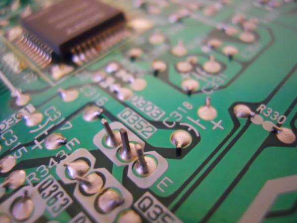
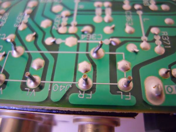
It would be useful to measure a couple of voltages at this point. Put your meter on DC volts and on a range high enough to read at least 50 volts. Connect the BLACK meter lead (make sure you have them the right way around in the meter too) to either the NEGATIVE speaker terminal or the metal chassis somewhere. Both should be at the same point electrically. Now with the amp on measure the voltage on Fuse 1 and Fuse 2. One is left output and the other right. Both voltages should be very very close to zero.
That's the first step. Report back with the voltage readings.
The second step is to see if the output stage is drawing current. Read the manual where it says "adjustment instruction". All you are doing here is measuring the voltage ACROSS each of the four 0.47 ohm resistors. For this you need to use BOTH meter probes of course so remove the black lead from the chassis and measure across each 0.47 ohm. Polarity of the meter here doesn't matter. All that happens is you will get either a minus or a plus result. The voltage should be around 2.4 MILLIVOLTS. Thats tiny so you will need the meter set to a range that can measure low voltages. The voltage may be somewhat wide of the mark and may increase as the amp is on. Thats normal. What we are looking for is a zero result or an excessively high result both of which indicate a problem.
Remember that an accidental short with the meter leads... I was going to say it happens to the best of us... (twitchy fingers)) will probably result in instant damage to transistors so take your time and be confident.
Again report back with the readings. We'll do it for BOTH channels so we know where we're up to. Those readings won't in themselves find the problem but they will give a good idea of the state of play and will get you used to handling the meter
All tests and measurements are done with NO speakers connected.
I'm assuming you have the amp with top and bottom covers removed for access. First step is a visual inspection for obvious problems such as dry joints. In particular look at the the leads on ALL the transistors. Spotting problems comes with experience but here's a couple of typical potential problems in these pictures. Notice how the solder is cracked in a ring around the component leads.
It would be useful to measure a couple of voltages at this point. Put your meter on DC volts and on a range high enough to read at least 50 volts. Connect the BLACK meter lead (make sure you have them the right way around in the meter too) to either the NEGATIVE speaker terminal or the metal chassis somewhere. Both should be at the same point electrically. Now with the amp on measure the voltage on Fuse 1 and Fuse 2. One is left output and the other right. Both voltages should be very very close to zero.
That's the first step. Report back with the voltage readings.
The second step is to see if the output stage is drawing current. Read the manual where it says "adjustment instruction". All you are doing here is measuring the voltage ACROSS each of the four 0.47 ohm resistors. For this you need to use BOTH meter probes of course so remove the black lead from the chassis and measure across each 0.47 ohm. Polarity of the meter here doesn't matter. All that happens is you will get either a minus or a plus result. The voltage should be around 2.4 MILLIVOLTS. Thats tiny so you will need the meter set to a range that can measure low voltages. The voltage may be somewhat wide of the mark and may increase as the amp is on. Thats normal. What we are looking for is a zero result or an excessively high result both of which indicate a problem.
Remember that an accidental short with the meter leads... I was going to say it happens to the best of us... (twitchy fingers
)) will probably result in instant damage to transistors so take your time and be confident.Again report back with the readings. We'll do it for BOTH channels so we know where we're up to. Those readings won't in themselves find the problem but they will give a good idea of the state of play and will get you used to handling the meter
Creative? Is it just a case of figuring out which pins go where?
Yeah. You'll have to bend the leads into the right places. Might need some insulation on the leads so they dont short.
Ok mate just waiting on the test meter to arrive. Looking forward to have a good poke about in there now . Il let you know how it goes.
Cheers again.
. Il let you know how it goes.Cheers again.
OK, so first things first and if your not sure on anything then ASK
All tests and measurements are done with NO speakers connected.
I'm assuming you have the amp with top and bottom covers removed for access. First step is a visual inspection for obvious problems such as dry joints. In particular look at the the leads on ALL the transistors. Spotting problems comes with experience but here's a couple of typical potential problems in these pictures. Notice how the solder is cracked in a ring around the component leads.
It would be useful to measure a couple of voltages at this point. Put your meter on DC volts and on a range high enough to read at least 50 volts. Connect the BLACK meter lead (make sure you have them the right way around in the meter too) to either the NEGATIVE speaker terminal or the metal chassis somewhere. Both should be at the same point electrically. Now with the amp on measure the voltage on Fuse 1 and Fuse 2. One is left output and the other right. Both voltages should be very very close to zero.
That's the first step. Report back with the voltage readings.
The second step is to see if the output stage is drawing current. Read the manual where it says "adjustment instruction". All you are doing here is measuring the voltage ACROSS each of the four 0.47 ohm resistors. For this you need to use BOTH meter probes of course so remove the black lead from the chassis and measure across each 0.47 ohm. Polarity of the meter here doesn't matter. All that happens is you will get either a minus or a plus result. The voltage should be around 2.4 MILLIVOLTS. Thats tiny so you will need the meter set to a range that can measure low voltages. The voltage may be somewhat wide of the mark and may increase as the amp is on. Thats normal. What we are looking for is a zero result or an excessively high result both of which indicate a problem.
Remember that an accidental short with the meter leads... I was going to say it happens to the best of us... (twitchy fingers
Again report back with the readings. We'll do it for BOTH channels so we know where we're up to. Those readings won't in themselves find the problem but they will give a good idea of the state of play and will get you used to handling the meter
- Home
- Amplifiers
- Solid State
- Vintage Toshiba 330 power amp problem, possible repair?