I'm trying to resurrect a Sansui 9090 , and am having trouble with the Amp Driver board. One channel trips the protector relay , so I'm leaving that one disconnected for now , the other works fine for a few seconds then becomes increasingly distorted . The DC control pot VR01 wants to be turned further clockwise than it will go , and the transistor TR05 gets very hot. Fusible resistor R29 gets fried if I leave it on any length of time. (It should be 390 R , I'm using 2.2K and 470R in parallel , is this ok for fusible?)
Any ideas as to what I should be looking at? The other thing I notice is that in the input from the power board to the driver board (and measuring without the driver board inserted), pins 3 and 16 are at 4 volts and 7 volts respectively , is this ok?
I thought about simply replacing the various transistors but having spent a lot of time on Google I find I'm faced with buying expensive originals on eBay because equivalents are so hard to track down. Has anybody made a list of substitutes for these old transistors anywhere?
Many questions , but I'm learning on the job here. Also , my multimeter continuity/diode test doesn't seem to work for some transistors , and I'm wondering if that is because it's cheap , has too high an impedance or just how things are.
")
Sansui
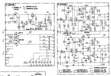
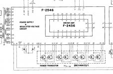
Yes , I suppose I'm assuming that those who are familiar with this receiver and have worked on it will have the schematic . Happy to hear from anyone else who wants to have a look , so here it is.
Yes , I suppose I'm assuming that those who are familiar with this receiver and have worked on it will have the schematic . Happy to hear from anyone else who wants to have a look , so here it is.
Attachments
OK...
The circuit is conventional (a quasi complementary) but one possible problem could be the driver transistors if these are faulty because they are a T066 package which is obsolete today. It may be possible to mount T0126 types with a bit of ingenuity. That is if they are faulty... they may not be. Suitable types spec wise would be MJE340/350.
TR5 and TR9 I can't find much on. These could be suspect too and I say that just based on experience that Japanese devices of this era in these type of packages inexplicably have problems as they age. Again I would say the MJE340/350 would be suitable here too.
For faultfinding I would apply a short across the vbe multipliers collector and emitter (TR07) as that will force the output stage to draw no current. The amp will still all work normally as long as nothing else is faulty.
You need to do a check of all the low value resistors that could have been damaged. The diode VD1212 in the constant current sink is an odd one. I suspect it will be two or three diodes in series in the one package. Thats something to check, that the current sink is working and the voltage across R37 is constant. Exact value depends on the voltage across the diode.
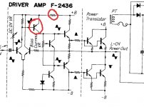
That transistor is the VAS (voltage amplifier stage). As mentioned, on something this age (and with experience of the failure mode of these old Japanese transistors) I think you have to start by replacing them with suitable alternatives. The outputs if they are OK are good to retain. I know that sounds a bit illogical but I've run across the Jap transistor issue many many times as a service tech... it happens. Only then can you move on and work on the amp properly.
- Status
- This old topic is closed. If you want to reopen this topic, contact a moderator using the "Report Post" button.
- Home
- Amplifiers
- Solid State
- Sansui 9090 help