Hi All,
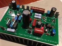
This is my latest little project. A "Fetzilla" derived design which uses no exotic parts and delivers about 85W RMS (42V rails). It sounds pretty good and does a near perfect rail to rail 20kHz square wave.
Although it's a rather conventional circuit with nothing new, the more unique elements are:
1) H2 heavy singleton input with current feedback.
2) CFP VAS with bootstrap CCS, run at nearly 40mA to drive the output fets directly with minimal loading.
3) Vgs multiplier for temperature compensation. Works perfectly.
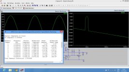
The amp can deliver oodles of current and has powerful bass, a forward mid range and clean treble. All in all, quite a nice little amplifier with a bigger and better sound than the schematic might suggest. The amp is thermally stable and stable into capacitive loads. It simulates quite well too, as the figure below shows.
Thanks to Hugh and Paul for their help and inspiration with this project.
This is my latest little project. A "Fetzilla" derived design which uses no exotic parts and delivers about 85W RMS (42V rails). It sounds pretty good and does a near perfect rail to rail 20kHz square wave.
Although it's a rather conventional circuit with nothing new, the more unique elements are:
1) H2 heavy singleton input with current feedback.
2) CFP VAS with bootstrap CCS, run at nearly 40mA to drive the output fets directly with minimal loading.
3) Vgs multiplier for temperature compensation. Works perfectly.
The amp can deliver oodles of current and has powerful bass, a forward mid range and clean treble. All in all, quite a nice little amplifier with a bigger and better sound than the schematic might suggest. The amp is thermally stable and stable into capacitive loads. It simulates quite well too, as the figure below shows.
Thanks to Hugh and Paul for their help and inspiration with this project.
Attachments
Last edited:
Hi Greg.
I think a Darlington VAS with the driver collector at ground would perform better than a CFP. Use only two resistors for bias current, one across the driver BE and another across the VAS BE, this way your VAS will have much less distortion as both transistors are NPN and the driver does not experience the collector swing of the VAS. The best driver has low Cbe and high Hfe - BC550C/2N5089/MPSA18. You will also have less potential problems with local CFP parasitics and positive feedback loops acting up.
In your configuration there is no local feedback at the CFP to speak of. This is because the impedance at the rail is orders of magnitude less than the impedance of T2's emitter, and so any potential feedback current sinks into the rail instead. So it acts basically the same as my Darlington above, except with much less current gain and more distortion because of both Early effect and Miller effect.
You have a very nice circuit there, Greg.1) H2 heavy singleton input with current feedback.
2) CFP VAS with bootstrap CCS, run at nearly 40mA to drive the output fets directly with minimal loading.
3) Vgs multiplier for temperature compensation. Works perfectly.
I had a look at schematic.
As you say nothing fancy, but only the transistors needed.
I am impressed with your results, squarewave and all.
Hope your thread here can make some more build a Fetzilla alike amplifier.
Because this topology works just fine.
I think a Darlington VAS with the driver collector at ground would perform better than a CFP. Use only two resistors for bias current, one across the driver BE and another across the VAS BE, this way your VAS will have much less distortion as both transistors are NPN and the driver does not experience the collector swing of the VAS.
Wow - I just simulated ur suggestion KT . . . . .
all HD is less than -110db in spice @ about 10W
I never saw anything like it before.
and rise time is much faster - neat idea ! . . .
. . . but 2nd at -115db is lower than 3rd at -110db - so will it sound musical ?
Wow - I just simulated ur suggestion KT . . . . .
all HD is less than -110db in spice @ about 10W
I never saw anything like it before.
and rise time is much faster - neat idea ! . . .
. . . but 2nd at -115db is lower than 3rd at -110db - so will it sound musical ?
I may sound different but those magnitudes of distortion are too low to be audible.
Wow - I just simulated ur suggestion KT . . . . .
Look at also Mooly's M1 HEXFET. Mooly took the feedback from the VAS and use CCS instead of bootstrap. By taking the feedback from output and running bootstrap instead of CCS, performance is also good.
Mikel, by changing the resistors I think you can change the harmonic profile.
At most frequencies I think the miller cap will be the dominant source of loading for the input stage, and this cap responds to the distortion of the output stage, which is why I think after eliminating VAS distortion the 3rd harmonic begins to dominate. Try a resistor from the output of the amp to the VAS input, this should add purely monotonic distortion. The only alternative to adding distortion is to reduce the distortion of the output stage, which would mean redesigning the circuit.
At most frequencies I think the miller cap will be the dominant source of loading for the input stage, and this cap responds to the distortion of the output stage, which is why I think after eliminating VAS distortion the 3rd harmonic begins to dominate. Try a resistor from the output of the amp to the VAS input, this should add purely monotonic distortion. The only alternative to adding distortion is to reduce the distortion of the output stage, which would mean redesigning the circuit.
Last edited:
Using a CCS may help, I'm not sure. If you take the bootstrap source from one of the FET sources, the bootstrap will produce dominant even harmonics.
I've built a few prototypes with the VAS done this way and they always sounded great, better I thought than a single-transistor VAS. This was with BJT amps.
I've built a few prototypes with the VAS done this way and they always sounded great, better I thought than a single-transistor VAS. This was with BJT amps.
Nice one Greg - can't wait to hear this one . . .
Thanks Mike. The sound isn't quite as magic as Fetzilla, but the lack of expensive or rare parts and twice the power make up for it I think.
Any chance to see a lateral version?
The idea of this design was to avoid using rare or expensive parts (laterals). However, it does work very well with them. Simply replace the VAS CFP/darlington with a single 2SC3503 as the extra gain is not needed. Change the bootstrap resistors to about 1.5 - 2k to drop the VAS current to 10mA. Drop the bootstrap cap to 220u. Replace the Vgs multiplier with a simple trimmer pot. Easy and works well.
I guess it depends on the device pin outs but if they are the same a lateral version would be simple - just replace the Vgs multiplier with a resistor - but since you have asked the question I'm guessing that the pins are different.
Yep, they are different.
I think a Darlington VAS with the driver collector at ground would perform better than a CFP.
Kean, my simulations don't show much of an improvement, though there definitely is one. However, the arrangement you mention sounds worse to my ears and I am told the clipping performance isn't the best which is why I went with the CFP design (even if "CFP" is a misnomer). That said this current circuit does stick a little when it clips on the negative half cycle anyway.
You have a very nice circuit there, Greg.
Thanks Lineup, your original fetzilla circuit is what got me on to the design so thanks for your inspiration!
Oh, I wanted to add.
I have experimented with constant current sources in the VAS quite a lot. I have no hesitation in saying that the boostrap CCS has less of the really deep low bass than an active CCS. It really does, and the difference is obvious. However, the bootstrap is less troublesome, reliable and brings out the mid range and provides clean treble.
It does something quite magic for vocals.
Really though, there's plenty of bass anyway, just not as much as with an active CCS, The bass which is there is well controlled and detailed, and the upper bass is wonderful.
With the limiting diode as shown in the schematic (thanks Paul), it also provides symmetrical clipping performance (sticking aside).
Oh, I wanted to add.
I have experimented with constant current sources in the VAS quite a lot. I have no hesitation in saying that the boostrap CCS has less of the really deep low bass than an active CCS. It really does, and the difference is obvious. However, the bootstrap is less troublesome, reliable and brings out the mid range and provides clean treble.
It does something quite magic for vocals.
Really though, there's plenty of bass anyway, just not as much as with an active CCS, The bass which is there is well controlled and detailed, and the upper bass is wonderful.
With the limiting diode as shown in the schematic (thanks Paul), it also provides symmetrical clipping performance (sticking aside).
You can have both, the bootstrap and the CCS, look here http://www.diyaudio.com/forums/solid-state/186981-bootstrapsccs-t-tmc.html
dado
Dadod,
We found that your method gave very strong bass but preserved the marvellous sound of vocals we noticed with simple bootstraps.
Good suggestion.....
Hugh
Thanks Hugh,
After some amps built with the CCS I am slowly returning to that method because, as you beautifully said, the marvellous sound of vocals.
Damir
Square wave
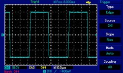
This is the 20kHz 60V p2p unloaded square wave. Unfortunately my scope overwrote the loaded square wave I captured but I can tell you that it is not as pretty and has quite a bit of droop. Still, the rise and fall times aren't too bad considering the lack of driver transistors. I will post the loaded wave when I get a chance to measure it again on the weekend.
This is the 20kHz 60V p2p unloaded square wave. Unfortunately my scope overwrote the loaded square wave I captured but I can tell you that it is not as pretty and has quite a bit of droop. Still, the rise and fall times aren't too bad considering the lack of driver transistors. I will post the loaded wave when I get a chance to measure it again on the weekend.
Attachments
re squarewave:
I think the rise times will be quite sufficient for a nice open sound.
I wonder, what your current thinking is about lead vs lag compensation ?
In spice lead always appears to out perform lag when dealing with a capacitive load. Did you try both with this design ?
I think the rise times will be quite sufficient for a nice open sound.
I wonder, what your current thinking is about lead vs lag compensation ?
In spice lead always appears to out perform lag when dealing with a capacitive load. Did you try both with this design ?
Hi Mike,
I must admit I have been a bit slack experimenting with compensation on this design. I tried 33pf of phase lag and it was stable from the get go.
33pf just felt right to me and I didn't experiment further. This is one place you might find some additional performance if you are willing to experiment. I might have a fiddle around with it on the weekend too. This design is far from optimised and really is just a proof of concept that:
a) We can successfully drive vertical fets from the VAS and still achieve reasonable performance - though "reasonable" is open to interpretation.
b) The Vgs multiplier works splendidly as a vertical mosfet temperature compensation scheme.
Now comes the challenge of refining and optimising the design!
- Status
- This old topic is closed. If you want to reopen this topic, contact a moderator using the "Report Post" button.
- Home
- Amplifiers
- Solid State
- Simple 85W amplifier