Greg.Dadod,
I like your CCS concept and tested it extensively when developing Fetzilla. I agree it sounds good. However, using a depletion mode fet was outside the scope of this project which called for the use of no exotic, specialist or rare parts.
Bootstrap of the VAS
is really a Blessing in simplicity.
If it gives god sound in any way it is a bonus.
Hi Mike,
I must admit I have been a bit slack experimenting with compensation on this design. I tried 33pf of phase lag and it was stable from the get go.
33pf just felt right to me and I didn't experiment further. This is one place you might find some additional performance if you are willing to experiment. I might have a fiddle around with it on the weekend too. This design is far from optimised and really is just a proof of concept that:
a) We can successfully drive vertical fets from the VAS and still achieve reasonable performance - though "reasonable" is open to interpretation.
b) The Vgs multiplier works splendidly as a vertical mosfet temperature compensation scheme.
Now comes the challenge of refining and optimising the design!
What I do (most of the time
") ), first use the amp (simulated and/or actual build) with no compensation and create a worst case unstable load, then compensate for it and find the smallest compensation that works, next select a compensation (capacitor or other) that is twice the value of the one that works.
), first use the amp (simulated and/or actual build) with no compensation and create a worst case unstable load, then compensate for it and find the smallest compensation that works, next select a compensation (capacitor or other) that is twice the value of the one that works.I think there are often two different modes of oscillation that need addressing and it is possible to take different measures for each of them.
1) Overall stability of the amp typically 10 - 20 Mhz
2) Stability with a difficult load often perhaps around 2.5 Mhz
I have found that lead compensation - typically across Rf - is more effective for load stability rather than lag compensation - and some people including JLH think that lead compensation sounds better.
Often some of each will be necessary.
Load stability often has little to do with the internal stability of the amp. If you try to increase load stability by changing the VAS miller comp you will probably end up with a sub-optimal value for performance because it affects the internal stability most. So I would use lead compensation to tune load stability and lag to tune internal stability.
Mike, Kean,
Yes, I agree. And, I have found ouput chokes to actually be beneficial in some cases. They provide a rounding to the top end which with my speakers presents as refinement.
GEirin,
Yes, I think the quasi version will be worth waiting for. The 85W amp I posted here does not match fetzilla's relaxed presentation and wastes 4-5v of the rail voltage as heat.
The quasi version is all transistor and will use only 60mA of bias or so. Should sound good and be quite efficient. Give me a few weeks.
Cheers,
Greg.
Mike, Kean,] . . . And, I have found ouput chokes to actually be beneficial in some cases.
Mmmm, I really must try o/p chokes some time. I never had an amp that needed them so I never got around to it.
Mike,
While I totally concede that on an objective basis they decrease the treble response, I find the effect quite pleasing and more natural to the ear. This may be due to my particular tweeters, but I think it is worth a go when one considers that the choke can be made on a stand alone basis and easily placed in and out of circuit.
While I totally concede that on an objective basis they decrease the treble response, I find the effect quite pleasing and more natural to the ear. This may be due to my particular tweeters, but I think it is worth a go when one considers that the choke can be made on a stand alone basis and easily placed in and out of circuit.
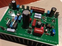
just noticed, is it ok to have outputs tight against the board ?
with just one output pair I expect they get quite hot when driven hard
Yeah, you're probably right. Having them clamped to the PCB probably is not the most thermally efficient.
However, the PCB acts like a big washer and ensures they make good contact with the sink. It's convenient for mounting the PCB and in reality I don't push the amp hard in normal listening.
Hi Guys
An output choke you can _hear_ is far too high in value for its purpose. Typical values are 2-10uH and are comprised of a few turns of fairly heavy magnet wire, either as an air-core or wrapped around a 1W resistor.
The plastic side of power devices gets very hot. Its poor thermal characteristics are what limit such packages to 25-50C lower operating temps than the same die in a metal case. Restricting airflow over the plastic is "a bad thing". It is "clever" - not in a good way - to clamp the devices between the PCB and the heat sink, but it has no advantage and risks burning the board. Once the board is carbonised it is trash.
The fact the plastic side gets so hot can be used to advantage when setting up thermal compensation devices. A TO-126 or TO-220 bolted to the plastic side of a larger package will be subject to much quicker heat changes, the only important one of which is at first power up.
I never use lag compensation - at least not since Cordell published his mosfet amp in 1982.
Have fun
Kevin O'Connor
Struth,
I agree completely that a choke you can hear is too big at least when it comes to objective measurements. However, if I was chasing objective perfection in my amplifiers I would not have sold my Doug Self Blameless amplifier on ebay. I like the sound of a fairly large choke. That's why I use them. I find it more natural sounding than applying excessive phase lag or lead compensation.
As for your comments on the devices being clamped under the PCB. I present the possibility that if your devices are getting that hot your heatsink is too small and your insulating washer too thick. I can point you in the direction of several successful commercial builders who use the same technique. Rod Elliot is one such example:
http://sound.westhost.com/p101-pic.jpg
Hi Guys
I never mount the output devices that way and neither do any builders I respect. The fact you see something done even by a mass producer does not mean it is good practice. Rather, it is just that they have decided that this compromise is one they accept.
Your choice to use an output choke as a treble control is valid for yourself. You can insert any type of EQ between the PA and speaker but you lose damping and introduce other distortions - all of which may alter the sound in a way you like. Personally, I prefer to eliminate as many things between the amp and speaker as possible, to the point of bi-amping and using active crossovers.
I am neither a pure objectivist nor a pure subjectivist. There is a need for both approaches in evaluation of audio equipment.
I've built a lot of simple amps, complex amps, different technologies and hybrids. Ultimately you search for the same result from each exploration - the sound that excites you.
You might like the blameless amp a bit better if you changed it from lag to lead compensation. There are other issues with that circuit that I've detailed elsewhere.
Have fun
Kevin O'Connor
Who knows, maybe an output coil DOES decrease distortion, and that is why Greg prefers one? After all we know current drive improves a speaker's distortion. I would not be certain of this without measuring. It may also provide an impedance fix to dampen a resonating voicecoil, as well as preventing EMI from entering the amp from the cable. Furthermore, I'm not sure whether Greg is talking about just a coil or a L/R Zobel. A lone coil would not necessarily be as effective against load stability so I would add it in addition to the Zobel.
I've found that an amp generally sounds best when compensation is tuned so that the output L/R is not needed. However this may change depending on loads, so an amp needs a zobel tuned to its specific needs to cover all loads unless you are sure you will use the amp and speakers only as a pair. The L/R should be seen as part of the amplifier's stability compensation and stability ensured while output shorted into various caps from 470pF-1uF. I have not needed more than 500nH for modern amplifiers.
If coil field is an issue but you still want the Zobel close to the board, you can mount the R on the board and then connect the L via a twisted pair to some other location, behind the heatsink perhaps.The important thing for the Zobel is that the in/out are taken right at the resistor leads, so there is minimal inductance in series with the resistor and it can damp to its full potential. The twisted pair could theoretically resonate with the inductor but I think the R will be sufficiently lower than the twisted pair insulation capacitance.
BTW, my computer crashed several weeks ago, and I lost my bookmarks. I know that at one point DIYAudio had an advertisement on the top of the page for a shop that sold cheap aluminum amp project cases, but I can no longer find the site. I would really like to find this site again.
Struth,
At the end of the day if the devices are not getting overly hot I can't see why the mounting scheme matters. I would not write off a designer or builder just because they don't mount devices the way I do.
Mine are not getting overly hot and I am happy enough with my mounting scheme.
While I'm sure your proposed modifications to the blameless amp would have worked wonders, I would never have been prepared to hit a $2-3k amplifier with a soldering iron just to find out. The person I sold it to is very happy I believe, and so am I!
Kean,
Yes, I was referring to an L/C combo. A large inductor is known to reduce damping factor at HF. I think I like the sound of this. Or perhaps, as you say, it is from reduced EMF being fed back into the amp. In any case with this particular amplifier and my speakers I find it preferable. I would not say that it is necessarily true for all amplifiers or all speakers.
Audio being the subjective thing it is, I can assure you both that I am probably the only person in the world who prefers the sound with the choke. So I'm not going to beg you to go try it and guarantee that it will sound better. But that's the nature of subjectiveness.
Until I can have acceptable overshoot properties without ridiculous lag or lead compensation I will continue to use them. To me the sound is more natural with the choke than with hundreds of pf of miller capacitance for example.
Not sure about the enclosure website, sorry.
I don't know whether the coil's effects are due to EQ, EMI, impedance, or distortion. I don't think it's EQ; I've used an EQ before. I've found a more "refined" sound usually comes from improving the AC behavior of the amp. However this could also be an aspect of your speakers. I guess you've tested this on various speakers and found the effects to be the same?
I always use shunt compensation now, I never use Miller. Shunt compensation presents a more natural output impedance to the speaker for one thing, and is also more immune to PSRR. Whenever I listen to my amps with miller compensation the treble seems muted, with little realism or soundstage. I find some EQ rolloff can help with this, I think it forces phase linearity while attenuating high order harmonics. I do this with BJT output stages, I don't know if it will act the same with FETS. I know that it should capitalize on the benefits of FETs because shunt compensation does not load the input stage when there is no output load. Have you tried it?
I always use shunt compensation now, I never use Miller. Shunt compensation presents a more natural output impedance to the speaker for one thing, and is also more immune to PSRR. Whenever I listen to my amps with miller compensation the treble seems muted, with little realism or soundstage. I find some EQ rolloff can help with this, I think it forces phase linearity while attenuating high order harmonics. I do this with BJT output stages, I don't know if it will act the same with FETS. I know that it should capitalize on the benefits of FETs because shunt compensation does not load the input stage when there is no output load. Have you tried it?
Let me expand a bit. For the last few years or so, I've listened to all of my music in mono. That's because my amp prototypes are good enough to make it not worth listening to anything else, and because I have not yet built a prototype with both channels. This is because either I don't have enough parts, or because the prototype is obsolete before I am ready to build the next channel. Lastly, they just sound so good already I don't feel a terrible need to have it in stereo. I've never listened to a real hi-fi system before, so maybe I just don't know what I'm missing.
Yet, my amp squeezes an incredible soundstage and realism out of that one cheap fullranger. People who drop in for a listen never realize it's not stereo. If you turn your head with one ear towards the speaker, the illusion is so powerful you will hear music in the other ear (psychoacoustics for sure). I recently discovered a BJT output stage that virtually eliminates crossover distortion better than any EC schemes I've seen, with the same number of parts as a triple EF. This improved the sound remarkably, but I still say that the compensation scheme takes most of the credit for the great soundstage, imaging, and realism. I use shunt compensation. I have a hunch two-pole miller compensation will have a similar effect, but I haven't tested it yet, mainly because I view shunt compensation as a better method from an engineering as well as sonic perspective. Not to oversell, I'm also partial to it because I independently studied it and discovered many things about it on my own because I couldn't find any good documentation on it. Some forumites seem to understand it, but they never talk about it or show interest. So, maybe my head is in the clouds.
I always wondered why there is so much interest in circuit topologies, yet so little interest in stability compensation topologies. It seems no one wants to mess with compensation or stability for some reason.
.......... I don't push the amp hard in normal listening.
you can expect it to be mounted on big heatsinks, and driven to the limit into 4ohm load
but anyone can just lift the board a bit more, and mount a suiting washer between board and power fet
its no problem
I use shunt compensation.
Hi KT,
Can you define "shunt compensation" ideally with an example
thx
- Status
- This old topic is closed. If you want to reopen this topic, contact a moderator using the "Report Post" button.
- Home
- Amplifiers
- Solid State
- Simple 85W amplifier