With regard to GregH2's liking a choke at the output of his amp, my experience is similar when some years ago I have heard a product called 'Pure Henry' sold by Hi-Fi News and Record Review, connected to the output of many an amp, transforming their sound to a more refined and tighter bass presentation, with a lower background noise. HN & RR claimed that this was designed by Ben Duncan and it exhibited near zero capacitance, negligible resistance and was a pure inductor.
I've only seen this done by one mass-producer. Most that I have seen has been by small manufacturers and some DIYs....I never mount the output devices that way and neither do any builders I respect. The fact you see something done even by a mass producer does not mean it is good practice. Rather, it is just that they have decided that this compromise is one they accept.....
It's characteristic of many low volume, quality audio power amplifiers, that they are used or sold into conservative domestic use. In many, even the heatsinks are overkill to the n'th degree, as this and similar measures satisfy the temperament and insecurities of many audiophiles who perhaps, aren't too sure what amplifier specifications really mean but bigger is always good, right?
In Fetzilla and perhaps this new amplifier of Greg's too, there is a nominal 0.4 deg/watt cooling rating available for each single stereo output pair and even at high power and bias, the boards will be well within rating. FR4 is good for 140C for 1 hr, the foil bonding slightly less - sometimes rated to 130C but for longer (hours) exposure. That might need to be derated to ~100C if you expected continuous hard work in pro. applications but that's highly unlikely with an audiophile amplifier.
I think that the shortest traces possible in a class AB output stage is a critical requirement. If that means placing transistors away from their traditional neat row along the PCB edge for fewer long weaving traces, so be it.
If the application is conservative, no question of 'dissing' sensible users of this sandwich mounting technique should arise, anymore than when they routinely used Silpads, Epoxy encapsulated semiconductors, thermoplastic films in capacitors or even phenolic PCBs, still specified by top-drawer Japanese Audio manufacturers.
"or even phenolic PCBs, still specified by top-drawer Japanese Audio manufacturers"
Though not always, but in some cases I have heard identical amplifiers (diy) made on FR4 and Paper Phenolic; the latter coupled with Carbon Film resistors rather than MFR, all other things being equal, sound warmer to my ears.
Though not always, but in some cases I have heard identical amplifiers (diy) made on FR4 and Paper Phenolic; the latter coupled with Carbon Film resistors rather than MFR, all other things being equal, sound warmer to my ears.
"or even phenolic PCBs, still specified by top-drawer Japanese Audio manufacturers"
Though not always, but in some cases I have heard identical amplifiers (diy) made on FR4 and Paper Phenolic; the latter coupled with Carbon Film resistors rather than MFR, all other things being equal, sound warmer to my ears.
one too many variables to know what item caused what effect !
I know different resistors can make a big difference to the sound . . . I suspect more of a difference than board material
Thanks Ian, I agree completely. Conservative design means some compromises can be made and in DIY we don't need to conform. This is one example.
Kean,
It sounds like we have a similar problem. Too many circuits and not enough time! I also listen in mono a lot and I really do believe you can predict how good an amplifier will sound in stereo from one channel. With Fetzilla I didn't have a stereo pair until the final version.
As for shunt feedback. If you are talking about a capacitor across the feedback resistor, then yes I have tried it. Without success. However I have realised recently that I probably needed a resistor in series with the capacitor, so I may give it another go. In my experience the value of the capacitor was critical to the point that I didn't even have enough values lying around to try. But again, I probably needed the series resistor.
Kean, you are one of the most knowledgeable guys on these forums and I would be very interested to see the circuit you are most happy with if you are willing to share it. Your compensation scheme and output buffer sound interesting.
Cheers,
Greg.
KT is not talking about lead comp across the Rf rather compensation cap & R from o/p of 1st stage to ground or rail I think but I do not quite get this idea yet when I tried it in spice today it either had no effect or made things much worse.
For Lead compensation Cx + 500R is a good starting point and should be OK so long as the amp is fundementaly stable otherwise a very small millar cap may be needed also. If the amp is tending toward fundamental instabilty lead comp can make things worse.
For Lead compensation Cx + 500R is a good starting point and should be OK so long as the amp is fundementaly stable otherwise a very small millar cap may be needed also. If the amp is tending toward fundamental instabilty lead comp can make things worse.
At certain times of both yours & my development of fetzilla I think our designs were very close to fundamental instability - eventually cured by increasing the gatestopper on the VAS mosfet. I now am using a 2k2 there.
In these circumstances lead compensation can make the amp sound worse or even burst into full blown oscillation.
So now that I have a fundamentally stable cct I will revisit lead compensation because in theory it should be better and it was the preferred method of JLH which makes me think it must have something going for it !
cheers
mike
Yes, I think you're right.
My solution was to tolerate the instability - no compensation of any kind, choose a VAS mosfet with very low transconductance (ZVP3310A), and then employ a largish output RL choke. I found this sound preferable to any other compensation scheme, stable into any load and absolutely zero square wave overshoot into capacitive loads. I intend to experiment with compensation more on my BJT amps where I think it will prove more useful.
My solution was to tolerate the instability - no compensation of any kind, choose a VAS mosfet with very low transconductance (ZVP3310A), and then employ a largish output RL choke. I found this sound preferable to any other compensation scheme, stable into any load and absolutely zero square wave overshoot into capacitive loads. I intend to experiment with compensation more on my BJT amps where I think it will prove more useful.
Mikelm, the Circlophone is another more straightforward implementation of shunt compensation. Get that one working and mess with it.
I could write a lengthy article about shunt compensation and amplifier stability, and that's what I would like to do. I would like to share my design with it, but if I am going to put my design on the net I want to be the first one to offer kits/boards, since I can no longer do this without some money for R/D.
While I may have a lot of understanding for amplifiers, I am not as knowledgeable as a lot of people here. For instance I struggle more on the mechanical and layout aspects of design. I'm still not sure how to properly determine the power ratings of an amp, and I don't totally trust all the common methods of doing so.
For instance I struggle more on the mechanical and layout aspects of design. I'm still not sure how to properly determine the power ratings of an amp, and I don't totally trust all the common methods of doing so.
We all have our weaknesses. Aside from not knowing much about the nitty gritty workings of an amplifier and semiconductors, I am absolutely terrible at PCB layout. I just can't get PCBs to look good AND have short signal paths. That part of my brain is missing...
Fortunately high levels of enthusiasm and a willingness to try often overcome such obstacles and make more progress than sitting on the fence. Another fortunate thing is that sometimes flaws are what make things sound unique.
I hope one day you will share your design. I am happy to share all mine because selling PCBs or kits is never going to be a viable alternative to my day job, as much as I wish it was - I enjoy it far more!
Member
Joined 2009
Paid Member
I am happy to share all mine because selling PCBs or kits is never going to be a viable alternative to my day job, as much as I wish it was - I enjoy it far more!
sometimes, turning an enjoyable hobby into a business can be a sure fire way to suck all the fun out of it. you have to make choices based on the hard cold reality of running a business. in a hobby we get to do what the heck we like. And that's really something in my view.
I only said I wanted to be the first one to offer kits, or just boards. It was just an idea. After all I DID design it.
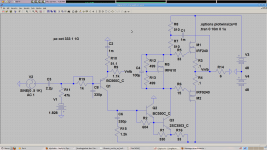
Try this Greg. If you do the bootstrapped FET thing the distortion is lower than 33p miller comp.
I think miller compensation might cause its own problems with FETs. With shunt compensation there is no capacitive short to the miller rail, so either the gate stoppers can be much lower or they will have to be much higher. I'm betting on lower.
Attachments
Kean, sorry, I was not criticising. I hope you do sell some PCBs.
Thanks for the schematic.
I am familiar with that compensation scheme though I have not tried it. Is it possible that you like the sound more because you don't have the local feedback provided by a miller cap and hence have higher THD?
Thanks for the schematic.
I am familiar with that compensation scheme though I have not tried it. Is it possible that you like the sound more because you don't have the local feedback provided by a miller cap and hence have higher THD?
Greg, why do you assume no miller cap means more THD? Local feedback cannot help the VAS because it's main purpose is to amplify the error signal. So by decreasing VAS gain you increase the size of the error signal, and you get more distortion. This is why we use as small a miller cap as possible, if it was a good thing we would use as big a miller cap that would fit on the board.
Last edited:
Kean, my interpretation of this line from cordell's book was that miller comp linearises the vas and hence would have lower distortion than the shunt variety:
Miller compensation uses local feedback to roll-off the high-frequency response of the amplifier. The gain that is “thrown away” acts to linearize the VAS with shunt feedback.
Miller compensation uses local feedback to roll-off the high-frequency response of the amplifier. The gain that is “thrown away” acts to linearize the VAS with shunt feedback.
Okay, keep thinking.
An amplifier might seem like a collection of discrete stages but once you close the feedback loop, everything changes. You must treat each stage in context.
If it was open-loop, the local feedback idea might apply, but when you close the loop, the VAS is no longer amplifying the signal. It is amplifying the error signal subtracted by the input stage. When you decrease VAS gain you are amplifying the error signal!
Without feedback we analyze the amplifier from input to output. With feedback let's analyze it from output to input. Each stage's job is to do the opposite of amplify in this sense. The output and VAS stages jobs are to attenuate the load stress so much that by the time it gets to the input stage, it is so small it does not affect the output voltage. Again, by decreasing output stage or VAS gain, you increase the error and distortion.
This "local feedback" idea makes little sense, except for open-loop amplifiers. Say you apply local feedback to the VAS, and halve its gain. Distortion would also be halved right? BUT, now your input signal must be twice as large for the same output, so distortion is just doubled again. BUT, because your source must drive twice as hard, you end up with twice as much distortion in the end!
The only real solution is to not cause distortion in the first place, or to reject distortion by proper use of impedances.

- Status
- This old topic is closed. If you want to reopen this topic, contact a moderator using the "Report Post" button.
- Home
- Amplifiers
- Solid State
- Simple 85W amplifier