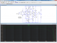
A well-known alternative is indirect voltage feedback at the input with a degenerated differential pair and a model degenerated differential pair. This example circuit is not designed to be flat up to 20 MHz, why do you want 20 MHz for audio anyway?
One snag: the waveforms during clipping can be rather nasty, especially when R7 is a little smaller than R8.
One snag: the waveforms during clipping can be rather nasty, especially when R7 is a little smaller than R8.
Attachments
A well-known alternative is indirect voltage feedback at the input with a degenerated differential pair and a model degenerated differential pair. This example circuit is not designed to be flat up to 20 MHz, why do you want 20 MHz for audio anyway?
One snag: the waveforms during clipping can be rather nasty, especially when R7 is a little smaller than R8.
Marcel, your linked schematic uses easily available parts, thanks. Can this be used as an Unbalanced to Balanced converter?
It is not exactly what I am looking for, almost the opposite in fact: it has an LTP input and requires a balanced output.A well-known alternative is indirect voltage feedback at the input with a degenerated differential pair and a model degenerated differential pair..
It is for a general purpose measurement amplifier, and I don't want to limit myself to audio onlyThis example circuit is not designed to be flat up to 20 MHz, why do you want 20 MHz for audio anyway?
Actually you can ground one output and take the signal from the other output. So you can use it as a balanced to unbalanced or unbalanced to balanced converter, whatever you want.
This specific circuit is not very suitable as a measurement amplifier because it was designed as an audio circuit. The response neither extends to 0 Hz nor to 20 MHz.
You can, though, use the general principle of putting a balanced input signal on a degenerated differential pair and the feedback signal on another degenerated differential pair and nulling the difference between their outputs. If you look in old Analog Devices instrumentation and video amplifier datasheets, you find some nice implementations meant for the 0 Hz to many MHz range. The advantage is that you can get a large CMRR without requiring ridiculously good resistor matching.
Agreed, but in general, I prefer to use a circuit that does natively what it is supposed to do.Actually you can ground one output and take the signal from the other output. So you can use it as a balanced to unbalanced or unbalanced to balanced converter, whatever you want.
For example, you could build a trike by removing a wheel from a four-wheel vehicle, but it will not make a very good trike.
Here, I start with a completely symmetrical signal (vertical and lateral symmetry of the source), which I want to amplify and convert into an asymmetrical one, but in fact this asymetrical signal is symmetrical about ground: it has a vertical symmetry.
Thus, I want to use the vertical symmetry already present in the input rather than having a mode-conversion.
In general, mode conversions tend to degrade something, and if possible, I prefer to avoid them when there are altrnatives.
I hope this doesn't sound too much like gobbledygook...
That is not really a problem, it could be adaptedThis specific circuit is not very suitable as a measurement amplifier because it was designed as an audio circuit. The response neither extends to 0 Hz nor to 20 MHz.
Yes, that is one my goals.You can, though, use the general principle of putting a balanced input signal on a degenerated differential pair and the feedback signal on another degenerated differential pair and nulling the difference between their outputs. If you look in old Analog Devices instrumentation and video amplifier datasheets, you find some nice implementations meant for the 0 Hz to many MHz range. The advantage is that you can get a large CMRR without requiring ridiculously good resistor matching.
Thanks for the contribution anyway, it gives me some other ideas.
If you look in old Analog Devices instrumentation and video amplifier datasheets, you find some nice implementations meant for the 0 Hz to many MHz range. The advantage is that you can get a large CMRR without requiring ridiculously good resistor matching.
I've used AD830 which I think has this architecture, in a DAC design. Sounded good to my ears. Can't recall though if its good to 20MHz but certainly its CMRR is exemplary to 1MHz.
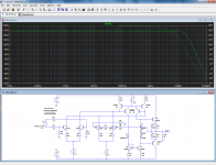
OK, here is the unbalanced-output, wide(r) bandwidth version.
It is good to ~10MHz. Going higher would require real HF transistors.
And as a bonus") , a slightly improved version of the original circuit with a more accurate 0V level at the output.
, a slightly improved version of the original circuit with a more accurate 0V level at the output.
If C1 is omitted, the outputs will behave like a grounded center-tap transformer's secondary.
It is good to ~10MHz. Going higher would require real HF transistors.
And as a bonus
, a slightly improved version of the original circuit with a more accurate 0V level at the output.If C1 is omitted, the outputs will behave like a grounded center-tap transformer's secondary.
Attachments
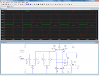
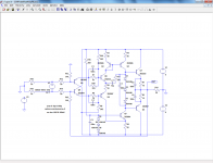
I built a quick prototype of the circuit I gave in the first post.
Here is the amended schematic after "real-life-corrections".
On the dynamic aspects, it does deliver: it is capable of putting out a clean 20MHz, 5Vpp squarewave into a 50 ohm load, which is quite impressive.
Its Achilles heel is the DC accuracy/stability.
Here is the amended schematic after "real-life-corrections".
On the dynamic aspects, it does deliver: it is capable of putting out a clean 20MHz, 5Vpp squarewave into a 50 ohm load, which is quite impressive.
Its Achilles heel is the DC accuracy/stability.
Attachments
OK, here is the unbalanced-output, wide(r) bandwidth version.
It is good to ~10MHz. Going higher would require real HF transistors.
And as a bonus
If C1 is omitted, the outputs will behave like a grounded center-tap transformer's secondary.
I deliberately gave the original a common-mode loop that is both weak (low transconductance) and slow (filtered by C1), so that the output behaves more or less like a floating voltage source at audio frequencies, that is, like a normal transformer secondary rather than a centre-tapped transformer secondary. That way you can use the output in single-ended mode without the common-mode loop needing to do anything with the signal, but you also keep the flexibility of using the output in differential mode. The accuracy of the DC common-mode level was rather irrelevant because I could use AC coupling. I designed it for a local radio station that uses both professional and consumer gear, and there it really comes in handy.
Anyway, your single-ended version looks nice and is definitely more suitable for your measurement application.
I built a quick prototype of the circuit I gave in the first post.
Here is the amended schematic after "real-life-corrections".
On the dynamic aspects, it does deliver: it is capable of putting out a clean 20MHz, 5Vpp squarewave into a 50 ohm load, which is quite impressive.
Its Achilles heel is the DC accuracy/stability.
How about the low input impedance and the resistor-matching-dependent common-mode rejection (which is probably not too bad because you have gain>>1)? Are you only measuring signals from very low impedance sources?
The low impedance is not a problem, it is a 50 ohm environment.
Having the common-mode dependent on resistor accuracy is not a problem for me (although I would prefer freedom from that constraint).
Anyway, I could also add a second Rush cascode for the feedback, very much like your circuit.
More annoying is the fact that the ultimate low frequency CMMR depends on the matching of Early effect in complementary transistors, mainly Q5 and Q6.
The 2N2222/2N2907 pair is quite good in this respect, they achieve more than 70dB up to 500KHz.
The poor DC stability is annoying too, and adding a DC servo would add a layer of complication.
All this is manageable, but I would like to find something friendlier
The low impedance is not a problem, it is a 50 ohm environment.
50 ohm is a characteristic impedance that isn't used much in audio applications, except in broadcast transmitters. Are you sure you are on topic?
Yes, because as I said, I am interested in topologies, and I remember having seen some unusual ones on this forum.50 ohm is a characteristic impedance that isn't used much in audio applications, except in broadcast transmitters. Are you sure you are on topic?
Some might be totally unusable above several hundreds of KHz, but others could perhaps easily reach tens of MHz by lowering resistance values, etc
- Status
- This old topic is closed. If you want to reopen this topic, contact a moderator using the "Report Post" button.
- Home
- Amplifiers
- Solid State
- Alternative topologies for balanced to unbalanced amplifier