The simplified version is the star is meant to minimize differences in "ground" potential and therefore the potential for ground loops. Practically we use a star of stars connecting one channel's grounds together and then retuning that to the central star. Follow the build guide for the connections to this board that need to return to the star.
The safety earth should always connect directly to the enclosure. Audio grounds should connect to the same spot. I like the idea of some isolation of the audio grounds from earth. Try the scheme Nelson Pass uses. Tie the AC connections of a 25A bridge rectifier together. Tie this to the safety earth. Connect the + and - terminals together and connect audio grounds to that. Connect a CL60 across the bridge. This allows about 10 ohms from audio ground to safety earth that helps prevent ground loop hum but will go to virtually zero if current flows between them in a fault condition.
The safety earth should always connect directly to the enclosure. Audio grounds should connect to the same spot. I like the idea of some isolation of the audio grounds from earth. Try the scheme Nelson Pass uses. Tie the AC connections of a 25A bridge rectifier together. Tie this to the safety earth. Connect the + and - terminals together and connect audio grounds to that. Connect a CL60 across the bridge. This allows about 10 ohms from audio ground to safety earth that helps prevent ground loop hum but will go to virtually zero if current flows between them in a fault condition.
I have had a PM asking me to tell what transistors and settings I used for the Honeybadger amp used in the stereonet review so thought I would post here so others can see as well. I will copy and paste from the original options.txt file ostripper produced.
The cascode (Q3-4) can be setup in 2 (or more) ways.
- The first is a zener referenced design - omit R18 , replace
with a 1/2w- 1w 12-15V zener diode and set jumper pad "C" to "Z" with thin wire. The "CRZ" jumper pads
are located above D1-2 near "OFFSET". You will have a cascode reference of either 12 or 15V , depending
on Zener diode choice.
The VAS , (Voltage Amplification stage) is what takes the small signal from the cascode/current mirrors and creates a
wide, rail to rail "swing" . With 60V supplies ,this can be a large as 110V peak to peak. This signal is also what you "hear"...
after the big devices of the output stage increase the current a 1000 times or more.
The "OPTIONS" here are numerous. The small CCS just has a 20 turn 200R trimmer(R7) , this CCS controls the LTP current , it can
be adjusted between 1.8ma to almost 6ma , optimum is 70-100R-R7 giving 3.5ma at the "tail" of the LTP.
The "BIG CCS" is a part of the VAS .... with R27=68R ,the VAS will have a current of about 9 mA. Other values-R27 are 100R=6ma(I used R27=100r) or
56R=10.5ma. These changes will affect the Bias of the amplifier , MAKE SURE "bias"-R30 is set at maximum 500R if you change R27!
The VAS itself has 2 compensation modes:
1. Conventional miller compensation (CMC)- Omit R24 - (the feedback 820R 1/4w resistor) , omit EITHER C7 or C8 replace one witha wire jumper and the remaining one with a 68pF 300-500v silver mica capacitor . So ... C8= jumper R24=nothing C7=68pF(as an example).
Don't install an LC capacitor(this made it sound worse).
Q13 was 2SC3953
Q14/15 are MJE15032/MJE15033
Transformer is 600w 40-0-40V
I used a single transformer supplying 2 separate power supplys, one for each channel. Each supply had 4 x 12000uf 63v Elna for audio caps and some 100nf bypass caps.
Most important for the great sonic character of this amp was to change the imput capacitor "C1". I used in mine a Clarity Cap SA 4.7uf.
Regards
Simon
Just some additional notes here.
Output transistors Q16-18 = NJW0281
Q19-21 = NJW0302
Transistors Q5 and Q6 I used BC556b Please note if using these instead of the usual KSA992 legs have to be bent around as KSA992 is ECB and BC556b is CBE) please be carefull.
Q1 - Q2 = MPSA18
C3 220uf 35v bi polar electrolytic panasonic (35-50v)
C4 I used MKP1837 ero 33n (this was experimental and no sound difference was heard)
R27 was 100ohm and adjusted for 0.6v (6ma)
Attached BOM.
That should be it..
Simon
Attachments
Last edited:
No.................The safety earth should always connect directly to the enclosure. Audio grounds should connect to the same spot. ....................
The Safety Earth connects to Chassis close to the input cable entry.
The Main Audio Ground is located to best serve the AUDIO components that are connected to it.
The Main Audio Ground DOES NOT need to be near the power input cable entry point.
It does not even need to be connected to Chassis.
It can be linked to Chassis with a wire or Disconnecting Network that can pass Fault Current.
Thanks for the correction Andrew. Connecting the safety earth to the chassis close to the cable entry is important, and I missed mentioning it because it was late.
I was trying to emphasize that the audio ground should only connect to the chassis at one point, NOT "a floor attachment be made at any convenient floor point" that the poster asked. Should have just said route all to one place.
 Lesson learned. No more posting from my phone with head on pillow.
I was trying to emphasize that the audio ground should only connect to the chassis at one point, NOT "a floor attachment be made at any convenient floor point" that the poster asked. Should have just said route all to one place.
Lesson learned. No more posting from my phone with head on pillow.We agree on that point Andrew, I guess I am not communicating well today.
I am trying to say to connect the audio grounds to a star ground - all connected to a single chassis point (star) or a star connected to the chassis at a single point. The various audio grounds should not connect to the chassis at multiple points of convenience.
I am trying to say to connect the audio grounds to a star ground - all connected to a single chassis point (star) or a star connected to the chassis at a single point. The various audio grounds should not connect to the chassis at multiple points of convenience.
Thanks for the "Grounding" advice. My enclosure internals have been positioned probably based more from a mechanical view point. So, consequently I am heavily reliant on the electronic expertise of others to explain some of the various subjective dilemmas as they occur.
It's all objective ? I actually figured out the proper way before Andrew explained
"why". Google is your friend ...
An externally hosted image should be here but it was not working when we last tested it.
Many good examples of OEM/DIY grounding techniques are available.
"Audio amp star ground" "[oem name} star ground" (search-images) ...
OS
Geez - who would have thought you could run out of room with the big case? Plug the power entry module into the back panel to see if you have clearance to the PSU boards. It may make sense to put the big transformers in the back and PSu boards up front. Otherwise looks OK to me.
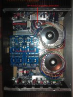
Here's my first dry fit of all the components in a 5U chassis. Any problems with this layout? Also, is it OK if the large toroids aren't sitting flush on the bottom plate?
Just an idea ...
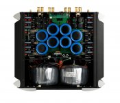
Mount toroids on front plate (example below - 10K$ "moon" reference amp
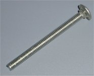
).Use carriage bolts to make it look good (2'nd pix)
OS
Attachments
I have created a wiring diagram, attached. I am building this dual mono, 63v rails, using the new v3 diyAudio PSU boards and Antek AS4445 transfos. Also, I am using a small toroid to power the speaker protector boards.
I have a few questions on this diagram:
Do I have the toroids wired correctly, for both the PSU's and speaker protection board?
Are the PSU boards grounded correctly? I saw a lot of options on the boards, and am very unsure of what I should be doing.
I'm not sure what the 0V in on the Badger boards is for.
Thanks!
Attachments
Be sure that the IEC ground connects directly to the case rather close to the inlet. The system ground can then connect to the case someplace convenient.
You might also consider lifting the system ground with a 35A bridge and CL60 like Nelson Pass does in many of his designs. This arrangement would go between the star and the case.
Don't the amp boards have a ground connection? AKA 0V - connect that to the star.
You can connect the purple wires on the big toriods to ground. It connects to the shield and should give you a bit better noise performance when connected to ground.
You're better off collecting them at one spot then connecting to the chassis. That spot can be different than where the iec connects.
RF presents more of a challenge but when i asked a friend to explain how ground wasnt all the same, he soldered both ends of a u shaped piece of wire to the ground plane of an rf amp be built. With a wire connected to a third spot on the ground plane he was able to draw a healthy spark from most of the raised "ground" wire.
RF presents more of a challenge but when i asked a friend to explain how ground wasnt all the same, he soldered both ends of a u shaped piece of wire to the ground plane of an rf amp be built. With a wire connected to a third spot on the ground plane he was able to draw a healthy spark from most of the raised "ground" wire.
Is the best technique to install a bolt in the bottom plate, ring terminals on all the ground wires, and star washers in between, then just stack them all up on the one bolt? I'm wanting a barrier block type of connection where many connections go to one but I've never seen one like that. Or maybe some kind of bus bar?
Gerber file
Hi,
Does anyone have a gerber file for the honey badger of OS 's design, I'm lucky enough to have access to a milling machine of my brothers, I don't really fancy I/p all those components into an auto router....
Btw fantastic reading the initial design forum pages...
Cheers
Mike
Hi,
Does anyone have a gerber file for the honey badger of OS 's design, I'm lucky enough to have access to a milling machine of my brothers, I don't really fancy I/p all those components into an auto router....
Btw fantastic reading the initial design forum pages...
Cheers
Mike
- Home
- Amplifiers
- Solid State
- diyAB Amp The "Honey Badger" build thread