OK I finally got around to testing the ripple on my Amps psu. I built a sound card pre-amp, and downloaded the freeware version of TrueRTA. What I see worries me somewhat!!! It looks real nasty!!!
So the question is: Is this real bad, and if so Is it likely my filter caps are cactus? There is 16,000uF capacitance on each rail, 2 X 8000uF.
Ive attached some screen dumps of what I saw in TrueRTA.
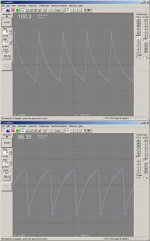
It's obvious to me the problem is at 50Hz which is what I would have expected, but the amplitude (around 100mv) seems a tad excessive, also the shape of the wave form is pretty weird, and seems to be mirrored +ve to -ve rail. BTW I have never used a scope before so wasn't sure what to expect!
The positive rail is the upper image and the negative rail the lower.
Regards,
Tony.
So the question is: Is this real bad, and if so Is it likely my filter caps are cactus? There is 16,000uF capacitance on each rail, 2 X 8000uF.
Ive attached some screen dumps of what I saw in TrueRTA.
It's obvious to me the problem is at 50Hz which is what I would have expected, but the amplitude (around 100mv) seems a tad excessive, also the shape of the wave form is pretty weird, and seems to be mirrored +ve to -ve rail. BTW I have never used a scope before so wasn't sure what to expect!
The positive rail is the upper image and the negative rail the lower.
Regards,
Tony.
Attachments
The measurements were taken with zero load (well 100ma quiesient current on the output transistors.
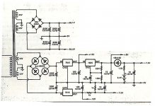
Here is the schematic. It's as basic as you can get, a metal can Bridge rectifier and some filter caps. The secondary 15V winding, and subsequent voltage regulators are fine, less than .5mv ripple, difficult to tell as the sound card has a bit of noise at that low a level. Note that the output voltage shown on the schematic is too high and is really around +- 63V.
The PSU drives two channels of my 100W Mosfet amp.
Regarding the 50Hz, is it supposed to be higher with full wave bridge rectififcation??? I just assumed that because the 240V was 50Hz, that would be the freq of the ripple.
Regards,
Tony.
edit: Forgot to mention the amp is 16 years old!
Attachments
Psu
Hi,
When building a PSU like this the two windings on the transformer are commenly out of fase, this in turn means that the caps are charged at the double freq of the mains.
The rippel you measured is only 50 hz, which leads me to think that the transformer has been (re)wired wrong??
Is there a problem with the amp?? the rippel is small
edit: try measuring the AC voltage between the two secondary windings, if you don't get something, the wirering is wrong
\Jens
Hi Jens,
There is (allways has been) a hum in the amp, although it isn't just 50Hz, as you can here it in the woofers, midranges, and tweeters. It bugs me as a friend built the same amp, and had no hum at all, so I have allways suspected there was a problem somewhere.
I'm not 100% sure what you mean by wiring the secondaries out of phase. I've often wondered whether it made a difference or not which ends of the two windings were wired together for the 0V line and whichs ends went to the rectifier, is this what you mean? I recently reversed the wiring (ie the two ends that were connected together for the 0V line I put to each side of the rectifier and the other two ends I made the 0V line. This didn't seem to make any difference to the hum problem though. Of course there are four possible combinations of wiring this up (without shorting a winding), and I don't know how to tell which way is correct. If you number the secondary wires from top to bottom in the scematic from 1 to 4 you could wire up 2,3 to zero volts, 1,3 to zero volts, 2,4 to zero volts, 1,4 to zero volts!
The transformer I got with the kit had the wrong coloured sleves on two of the secondaries, and if wired up the way the instructions said, had one of the secondaries shorted (ie 1,2 to zero volts, 3,4 to rectifier) so I have never been sure which of the above combinations I should use!
I thought that 100mV seemed high (Note I don't know what is low and what is high which is the main reason I started the thread") ), I tested some really cheap plug packs (admittedly only 12V) and they only had about 17mV ripple, so I was assuming that must be bad (as they are unregulated plug packs with little smoothing) , I was expecting with the amount of smoothing capacitors that I would get much less rippple than what these cheap plug packs had, so when I saw 100mV I thought it was REALY bad
), I tested some really cheap plug packs (admittedly only 12V) and they only had about 17mV ripple, so I was assuming that must be bad (as they are unregulated plug packs with little smoothing) , I was expecting with the amount of smoothing capacitors that I would get much less rippple than what these cheap plug packs had, so when I saw 100mV I thought it was REALY bad
On the measuring the voltage accross the secondary windings, I assume you mean the voltage accross the rectifier? If the transformer windings are in phase, then this will read what 0V? (I assume if they aren't out of phase, it will be around 90V?) I'm just trying to visualise what happens here, DC voltages I can cope with easily, I haven't really ever thought much about AC and the effects of phase.
Not going to be able to try measuring the voltage tonight, Its a major operation to get at the PS in this amp It's a public holiday tomorrow though so I might have a go at it then (and measure some more stuff with the scope while I'm at it, might shed some light .
Regards,
Tony.
There is (allways has been) a hum in the amp, although it isn't just 50Hz, as you can here it in the woofers, midranges, and tweeters. It bugs me as a friend built the same amp, and had no hum at all, so I have allways suspected there was a problem somewhere.
I'm not 100% sure what you mean by wiring the secondaries out of phase. I've often wondered whether it made a difference or not which ends of the two windings were wired together for the 0V line and whichs ends went to the rectifier, is this what you mean? I recently reversed the wiring (ie the two ends that were connected together for the 0V line I put to each side of the rectifier and the other two ends I made the 0V line. This didn't seem to make any difference to the hum problem though. Of course there are four possible combinations of wiring this up (without shorting a winding), and I don't know how to tell which way is correct. If you number the secondary wires from top to bottom in the scematic from 1 to 4 you could wire up 2,3 to zero volts, 1,3 to zero volts, 2,4 to zero volts, 1,4 to zero volts!
The transformer I got with the kit had the wrong coloured sleves on two of the secondaries, and if wired up the way the instructions said, had one of the secondaries shorted (ie 1,2 to zero volts, 3,4 to rectifier) so I have never been sure which of the above combinations I should use!
I thought that 100mV seemed high (Note I don't know what is low and what is high which is the main reason I started the thread
), I tested some really cheap plug packs (admittedly only 12V) and they only had about 17mV ripple, so I was assuming that must be bad (as they are unregulated plug packs with little smoothing) , I was expecting with the amount of smoothing capacitors that I would get much less rippple than what these cheap plug packs had, so when I saw 100mV I thought it was REALY bad On the measuring the voltage accross the secondary windings, I assume you mean the voltage accross the rectifier? If the transformer windings are in phase, then this will read what 0V? (I assume if they aren't out of phase, it will be around 90V?) I'm just trying to visualise what happens here, DC voltages I can cope with easily, I haven't really ever thought much about AC and the effects of phase.
Not going to be able to try measuring the voltage tonight, Its a major operation to get at the PS in this amp
It's a public holiday tomorrow though so I might have a go at it then (and measure some more stuff with the scope while I'm at it, might shed some light .Regards,
Tony.
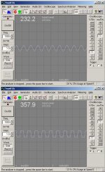
ripple with load
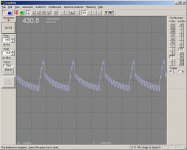
OK I haven't checked the wiring of the PS yet, but I decided to do a test with a load.
Input signal 1Khz sine wave at about .2V (all the soundcard will deliver) amp cranked to max volume, resulting in a 1Khz sinewave at speaker terminal at about 20V. Driving one channel only into 14 Ohm resistor (what I had lying around).
Now this looks much more nasty to me, but again, I don't know what to expect.
Attachments
soren said:Since you are using a full-bridge rectifier, the fundamental of the LF supply ripple hsould be 100Hz when using 50Hz mains. Are you shure you have wired up the rectifier bridge correctly?
Well I think so, but I'm no longer sure!!!!! I would have thought that if I didn't wire it up correctly that I wouldn't get the correct rail voltages???? I'm actually thinking about going out and buying two new rectifiers and wiring up a dual rectifier setup one each for +ve and -ve rails. This may help with my problem about not being sure which end of each secondary winding is which (if it even matters).
I guess it is possible that the rectifier bridge is faulty..........
Regards,
Tony.
edit: I am interpeting the cro output correctly aren't I. 5 peaks in 500ms (50 divisions of 10ms each) must be 50Hz correct?
Well I'll be damned. I just checked the ripple on the other rectifier in the amp and guess what. 100Hz ripple! I'm now wondering whether the main rectifier has been wired up incorrectly for the last 16Years, and if that's been the cause of all my Hum problems!!!!!
I must admit that I was building this amp late at night when I was supposed to be doing uni assignments, so it is quite possible I wired up the rectifier incorrectly, but never realised, because the voltages seemed to be ok. Time to pull the amp to bits me thinks!!!!!
Regards,
Tony.
I must admit that I was building this amp late at night when I was supposed to be doing uni assignments, so it is quite possible I wired up the rectifier incorrectly, but never realised, because the voltages seemed to be ok. Time to pull the amp to bits me thinks!!!!!
Regards,
Tony.
10A is a bit of a low rating for use with a 2x100W amp. 10A may seem like enough but it is marginal for power on surge currents. This leads me to the speculation that one or two elements may be damaged. I think (just think mind you) that if only half the bridge is blown while the other is OK you end up with a half-wave rectifier. That would explain ripple at 50Hz.If ypu have a diode tester on your DMM you can check this out. But in any case, if I were in this situation I would replace it with a 25A unit regardless.
With the power OFF and the unit UNPLUGGED and the filter caps discharged you can use an ohm meter to figure out which two leads should be tied together to make the center tap. When it is connected correctly the resistance reding between the ceneter tap and each of the other two leads will be equal while the resistance between the two non-CT leads will be double that of either of the CT-to-(+/-) leads. You may have to try a couple of permutations untill you find the arrangement that behaves like this. If none of the possible combinations reads this way the transformer is kaput.
With the power OFF and the unit UNPLUGGED and the filter caps discharged you can use an ohm meter to figure out which two leads should be tied together to make the center tap. When it is connected correctly the resistance reding between the ceneter tap and each of the other two leads will be equal while the resistance between the two non-CT leads will be double that of either of the CT-to-(+/-) leads. You may have to try a couple of permutations untill you find the arrangement that behaves like this. If none of the possible combinations reads this way the transformer is kaput.
progress I think
Hi Sam,
I just got back from Jaycar and purchased a 400V 35A bridge, will use it. I tested the existing bridge but it seems fine. I also went back to what Jens said originally about the phase, and voltages, and measured the voltage across the 15V rectifier, and it was around 30V. Measured the voltage across the 45V rectifier and it was 0V changed the center tap wiring around and it now reads 96V! The transformer is now actually putting out 48V per secondary with no load, was 47 before.
Am in the process of re-wiring it up. I have a feeling that some problems I've been living with for the last 16 years maybe about to go away....... heres hoping! I'm amazed the thing worked at all!!!!
Regards,
Tony.
Re: Transformer in fase
Thanks Jens,
I've now got 100Hz ripple at about half the level it was before. (about 48mV no load). and about 138mv with the same load as I tested above, ie 1Khz sine wave 14 Ohm resistive load which is much better than the 430mV before. I havent hooked the amp up to my speakers yet, but I suspect I that the hum problem hasn't gone away :-( Still can see spurious junk on the speaker output even with the volume knob at zero.
Thanks for the help, at least one problem now appears to be fixed .
Regards,
Tony.
JensRasmussen said:If the two secondary windings are in fase, they are just in parallel, this means that the bridge will work as a ½ wave recitifier.
Half wave rectifiers (even in a bridge box) will give you 50 Hz ribbel.
Hope you cure your amp
\Jens
Thanks Jens,
I've now got 100Hz ripple at about half the level it was before. (about 48mV no load). and about 138mv with the same load as I tested above, ie 1Khz sine wave 14 Ohm resistive load which is much better than the 430mV before. I havent hooked the amp up to my speakers yet, but I suspect I that the hum problem hasn't gone away :-( Still can see spurious junk on the speaker output even with the volume knob at zero.
Thanks for the help, at least one problem now appears to be fixed
.Regards,
Tony.
The fact that you now see 100Hz ripple is good. At least one thing has been taken care of.
Given the age, 16 years, another thing I would tink about is the condition of the electrolytic capacitors. Niot just the ones in the power supply but the ones in the amplifier whose function is to be a low resistance path between the rails and ground. These are smaller and a lot less expensive than the large smoothing caps in the PS. Unfortunately what you really need is an ESR meter. These are not too common and the ones you can buy off the shelf are expensive. There is a kit called the "Dick Smith ESR meter" that I've found really useful.
As an alternative it may be cheaper abandon attemps at a diagnosis just to replace the electrolytics - again I'm not talking about the large smoothing caps which are relatively expensive. On occassion, I've corrected a hum by this means. It's not a very sophisticated method and may not change anything. It has the advantage of being cheap in terms of time and money. Even if it doesn't make a difference one possable expanation is eliminated. For the less brilliant of us sometimes the only way to get where we want to be is to keep eliminating possabilities until the only thing left is the answer.
Thanks Guys,
Sam you are probably right about needing to replace the electrolitics. There are a quite a few but not too many, should be able to do it without too much expense. I should also try something that I found in another thread, which was to replace the caps in the RLC network on the output. There was another guy whose amp was humming and it was these caps that were the problem, the amp was oscilating at 3Mhz (unfortunately can't measure that with a pc base cro), and causing the hum. The weird thing is though that I have had the hum problem since day one, it hasn't got worse over time.
It's not really that bad, you need to get within about 30cm of the speakers to really notice it when the volume is at zero, but it is quite apparent when the volume is at maximum.
SSS, I did actually check the quesient current recently (about two months ago. It was out, can't remember if it was too high or too low, I reset it to the spec of 100ma but no real difference. At the time I was trying to track down a distortion problem, but it turned out to be my DVD player and not the amp.
Jens Will do some more measurements and post the pics. I bought some 15 Ohm 10W resistors the other day to simulate a reasonable load (ie about 7.5 Ohms). Will put the sine wave in at 1Khz both chanels and do the measurements again.
One thing I did notice was that the sine wave superimposed itself on the ripple much more prominently on the -ve rail than on the positve rail, unfortunately I didn't think to look at the ripple on both rails with the sine wave before I changed the setup doh!
The amp is back in service at the moment (the sound out of the TV isn't so crash hot, so I put it back). Probably won't be able to get to it for another couple of days, as it is a real pain to unplug and lug upstairs to the pc
I'll also post a pic of the "noise" on the speaker outputs. Its kind of weird (IMO) I guess it's not really hum, as there isn't any waveform so to speak, just spikes. Hmmmm might not be doing any measurments for a little while, my new cro probe just broke!! The earth leads connect just fell off. Back to the store for it!
Regards,
Tony.
some more pics
OK I have fired up the test gear once again. Bit more of a real world test now.
1Khz sinewave as before (input to preamp at .2V, managed to get the sound card to crank out .6V but caused the amp to clip severly, so I went back to .2V which is what I had in the previous test, at which setting the volume to max, causes slight clipping at the output.
Both channels are being driven, with two 10W 15 Ohm resistors in parralel as the load for each channel.
Having done this I now have another observation, clipping is occuring with only about 27V appearing on the speaker output, which is less than half the supply rail voltage, is that normal? Also at around the point when the amp starts to clip, it is making a funny noise, I'm not sure what component(s) are making the noise but its like something metal is vibrating a bit like a tuning fork..........
Finally the supply rail voltage goes down as I crank up the volume, starts at around 63V but drops to about 49V by the time the amp is fully cranked up (this is with .6V input 1Khz sine wave, with the amp clipping.
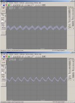
Anyway I have attached the latest test pics. As you can see the ripple is much more under control than it was with the transformer wired up incorrectly. And what's more, this is driving two channels, into roughly half the resistive load, so overall it is working a lot harder. I still don't know whether I should be seeing the 1Khz sine wave superimosed on the ripple though!!!
I spent a lot of time today looking up Farnel Australias web site, to get a list of caps to replace in the aging power amp section. I'm going to replace all of the electros with Panasonic FC series caps, and also the greencaps with some somewhat experimental Metallised Polyphenylene Sulphide (PPS) capacitors by Evox Rifa (If anyone has used these and they are bad news let me know and I go back to some metalised polyproylene ones!) and some .1uf ceramics to use as snubbing caps on the recfifier bridge.
The upper screen shot is the -ve rail and the lower the +ve rail.
Regards,
Tony.
OK I have fired up the test gear once again. Bit more of a real world test now.
1Khz sinewave as before (input to preamp at .2V, managed to get the sound card to crank out .6V but caused the amp to clip severly, so I went back to .2V which is what I had in the previous test, at which setting the volume to max, causes slight clipping at the output.
Both channels are being driven, with two 10W 15 Ohm resistors in parralel as the load for each channel.
Having done this I now have another observation, clipping is occuring with only about 27V appearing on the speaker output, which is less than half the supply rail voltage, is that normal? Also at around the point when the amp starts to clip, it is making a funny noise, I'm not sure what component(s) are making the noise but its like something metal is vibrating a bit like a tuning fork..........
Finally the supply rail voltage goes down as I crank up the volume, starts at around 63V but drops to about 49V by the time the amp is fully cranked up (this is with .6V input 1Khz sine wave, with the amp clipping.
Anyway I have attached the latest test pics. As you can see the ripple is much more under control than it was with the transformer wired up incorrectly. And what's more, this is driving two channels, into roughly half the resistive load, so overall it is working a lot harder. I still don't know whether I should be seeing the 1Khz sine wave superimosed on the ripple though!!!
I spent a lot of time today looking up Farnel Australias web site, to get a list of caps to replace in the aging power amp section. I'm going to replace all of the electros with Panasonic FC series caps, and also the greencaps with some somewhat experimental Metallised Polyphenylene Sulphide (PPS) capacitors by Evox Rifa (If anyone has used these and they are bad news let me know and I go back to some metalised polyproylene ones!) and some .1uf ceramics to use as snubbing caps on the recfifier bridge.
The upper screen shot is the -ve rail and the lower the +ve rail.
Regards,
Tony.
Attachments
clipping demo
OK Here is the screen dump showing no clipping and clipping.
I measured the input to the power amp (from the preamp) at about 3.3V with no clipping evident at that point. again this is a 1Khz sine wave.
as you can see at around 23V (I have my sound card preamp set to divide by 100) there is no clipping, at full volume and about 35V clipping is very evident (note that I haven't recalibrated the software for the divide by 100, and a measurment with the multimeter showed about 38V at full volume).
I just realised that the supply rails are at 63V DC but the output at 38V on the speakers is AC dohhhh...... so me thinking I should be able to get up to 63V without clipping is probably completly not based on reality.
One last intersting observation, I have a piece of blue tack on the amp beside the volume control. This is the do not turn up above this line mark which was supposed to stop people at parties from blowing my speakers, I can't remember how I decided on this point (it wasn't through any scientific means) but It is at this exact point that the amp starts minor clipping! So all those people in the speaker formum that told me I was most likely clipping my amp when I blew speakers, you were absolutely correct
Regards,
Tony.
Attachments
One more thing
I just measured the current on the speaker output whilst clipping 5A! so by my calculations 5A 38V is around 190W..... No wonder my poor speakers blew up!!!!
without clipping its about 3.8A at 29V so that's about 110W so I guess I can't complain about that
I guess that also explains why the two 10W wire wound resistors in parallel got a bit warm
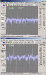
Also Ive attached a screen shot of the noise on the output of the amp with no input signal, top pic is with volume at zero and bottom is with volume at max. This is the worrying thing, If it was purely hum, I would have expected a sine wave, but its really spikey rubbish............
Regards,
Tony.
I just measured the current on the speaker output whilst clipping 5A! so by my calculations 5A 38V is around 190W..... No wonder my poor speakers blew up!!!!
without clipping its about 3.8A at 29V so that's about 110W so I guess I can't complain about that
I guess that also explains why the two 10W wire wound resistors in parallel got a bit warm
Also Ive attached a screen shot of the noise on the output of the amp with no input signal, top pic is with volume at zero and bottom is with volume at max. This is the worrying thing, If it was purely hum, I would have expected a sine wave, but its really spikey rubbish............
Regards,
Tony.
Attachments
- Status
- This old topic is closed. If you want to reopen this topic, contact a moderator using the "Report Post" button.
- Home
- Amplifiers
- Solid State
- Power supply problem???