Okay so I recently bought an old 70's amp made here in New Zealand by National/Panasonic. Quite a decent looking amp, large transformer, steel chassis, nice wooden cabinet and aluminium front panel, typical styling of the era etc. Turned it on and apart from a slight mains buzz (yet to be investigated, related problem maybe?) it seemed to work fine and sounded nice.
Then I noticed its temperature. Just being turned on and idle, the output devices started to get very hot, too hot to touch. I measured the voltage over one of the 0.45 ohm emitter resistors, and measured .67V, that works out at almost 1.5A idle current! I turned it off immediately, and started to examine the board for a bias trimpot. I find where one would normally go, but instead had two fixed resistors installed in place of a pot. Funnily enough, the pcb was designed to use two discrete resistors or a trimpot, each having their own dedicated through holes, so it was made like this at the factory.
I found a 5k trim pot that fitted in the space, and replaced the resistors and installed the pot. Using the pot I was able to bring the idle current down to around 1A but no lower.
Both channels were set up the same and exhibited the same behaviour, would there likely be some fault in this amp or is it possibly a class A amplifier? I can't find any info or schematics on the net at all, so am not really sure where to start looking other than removing and testing each component etc. Its quite obvious that its producing much more heat than it was designed to. I have looked and could not find a bias diode, so its probably using a transistor. If the bias transistor blew, would it maybe cause similar symptoms? Any help on this would be greatly appreciated.
With both channels the same I would suspect it's class A or A/B and biased well into A. So why do you say "Its quite obvious that its producing much more heat than it was designed to."? Does it not have sufficient heatsink? If it is class A, I would expect it to have a lot of heatsink. Another clue might be high wattage or current (fuse?) input rating compared to power output watts rating.
So why do you say "Its quite obvious that its producing much more heat than it was designed to."?
Have Panasonic ever designed an amplifier in real class A?
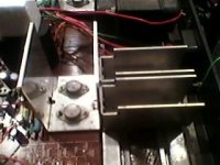
Thanks for your replies. It is definitely made for 240 VAC, as it was made in New Zealand. The heatsinks consist of a flat piece of aluminium sheet bent into a large U shape with the two output devices mounted on the bottom, and to one flat side of the U there are two more similar heatsinks mounted lengthwise. Hard to explain clearly, so have drawn a diagram that hopefully better explains it.
Pretty simple, 3 bits of sheet bent in a U, the ends of two of them joined to the side of one. In the diagram, the dotted lines show the edges etc, and the two red circles indicate the position of the two output devices. There is one such heatsink assembly per channel.
Model number is National NM27-114. Its a nice looking amp, and I was going to start the process of replacing the DIN connectors with RCA's and binding posts, but then I noticed how hot it was getting. Compared to the likes of a Musical Fidelity A100 which has a similar output arrangement designed to be biased into class A and uses the entire case as a heatsink, the heatsinking on this amp is pretty minimal.
Attachments

Last edited:
place pictures of your amplifier ...true documentation is hard to find for this machine
To my understanding here was never a Class A made amplifier from National but i might be wrong ....
There is a number of reasons for this to happen but first i dlike to see some pictures
kind regards sakis
To my understanding here was never a Class A made amplifier from National but i might be wrong ....
There is a number of reasons for this to happen but first i dlike to see some pictures
kind regards sakis
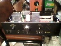
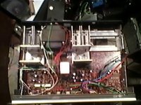
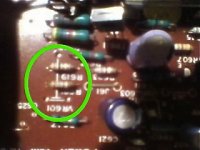
Okay, I have a uploaded a few photos of the amp. Sorry the quality is not very good, I only have my phones vga camera. Should give you an idea of what it is anyway. In one of the photos I have put a green circle around where there is provision for a trimpot to be mounted, with the two resistors in place.
Attachments
from power supply and heatsink view there is no chance that this is a class A amplifier
reason for "over biasing" could be any shorted transistor or capacitors ...your amplifier is too old so one way or another capacitors will need to be replaced
you also need to check if there is offset in the outputs that will also be an indication of trouble
photos you placed are to small to see anything from
kind regards sakis
Okay then, I have some interesting news regarding this amp. yesterday I thought to myself "maybe the amps oscillating" so today went and plugged it in, measured the bias, and whoa, its a fairly normal 15 mA. I wasn't sure what to think, so played some music, and then noticed it started to get hot, so I disconnected the music source and speakers and put the scope on the output, and measured a very high freq. sine wave, with the frequency reader on my multimeter giving a reading of almost 1.3 MHz! No wonder the amp was getting toasty.
Something odd I noticed was if I powered the amp up with the volume control down, then it would behave fine, and not oscillate and sounded normal. If I powered the amp up with the volume control even just at 8-9 o'clock setting then it would start oscillating, and moving the volume control had no effect on the output.
The next step was to disconnect the 0.68 uF capacitor that coupled the preamp output to the power amp input, and I found the amp stopped oscillating, or so I thought.
If I probed the input to the power amp with the probe attenuator set to 1x the amp would oscillate whenever touched by the probe. If I had the probe set to 10X attenuation then it would behave fine. I had the multimeter over the speaker out to give the freq. reading, and the scope would pick up the same oscillation through the input. The scopes input capacitance is 25 pF, and it seems that is enough to trigger the power amp into oscillation.
When I tested the output of the preamp, I was also getting oscillation but it would go away after a while and after a few power cycles of the amp stopped altogether.
I have replaced most (bar a couple that I didn't have, will be buying them tomorrow) electrolytic caps throughout the whole amp. Is it possible that some of the other caps need replacing? Where do I start to track the fault? As it is, the power amp wants to oscillate when a capacitive load is placed on its input, yet if I power the amp up with the volume control down, it seems to play fine without getting hot etc. Does anyone have any ideas on this?
I'm only guessing, but here goes.
Check the input stage for filtering.
There should be both a high pass filter (blocks DC and attenuates very low frequencies) and a low pass filter (attenuates Radio Frequencies).
Check also that the input to the amplifier (probably the base of the first transistor) has a low impedance source load to signal ground. This could be a small capacitor that doubles up as your low pass filter.
Check also what the amplifier sees looking back to source, when the source is unplugged.
Hi, if the bias is set by a transistor it should be located near the heatsink and be in thermal contact with it, in order to adjust the bias accordingly to the heatsink temp. If this transistor is shorted out the bias voltage will drop to zero and consequently no idle current in the o/p stage. In the case the transistor is open circuit then the o/p stage 'll be over biased therefore a heavy idle current 'll flow.
I have seen in some amplifiers the use of an NTC thermistor in the bias circuit which is also in thermal contact with the heatsink.
I have seen in some amplifiers the use of an NTC thermistor in the bias circuit which is also in thermal contact with the heatsink.
- Status
- This old topic is closed. If you want to reopen this topic, contact a moderator using the "Report Post" button.
- Home
- Amplifiers
- Solid State
- Amplifier problem, 1.5A Bias current ?!