Hi guys. So, i need some help to do a circuit analysis about the circuit i'll show below. The goal is to build a Class AB amp as simple as possible, aplying the learned concepts (that isn't too much) to require something around 5-10W on the output...
Here follows the schematic:
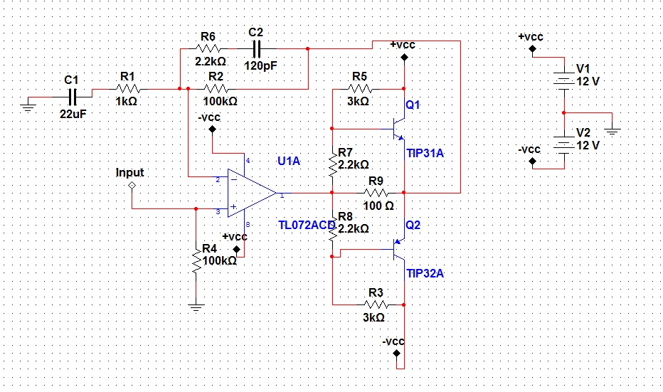
About this schematic... something is wrong? should be fixed? How much power will i get on the output? and the current gain about the 3th stage?
Here follows the schematic:
About this schematic... something is wrong? should be fixed? How much power will i get on the output? and the current gain about the 3th stage?
Attachments

It's not ideal, although great for learning.
The TL072 isn't suited to this type of circuit due to very limited output current capability. At the very least you would need darlington outputs.
I haven't calculated the bias network but that looks non ideal too. You need emitter resistors to provide some stability (0.47 ohm for example).
R9 I take it is to enable the opamp to drive the load at low levels thus minimising crossover distortion. In practice it will just load the opamp to much.
As I say, it's great for learning but you can do so much better if you want it for music reproduction.
what opamp would you recommend? the bias network i see isn't stabilized, i'll put the divider to provide some 0,7~0,9V on the bases.
I tought about darlingtons too, but they don't have some problemas with temperature, like excessive heating? what you think about connect more tip31 on parallel? like base to base..
And, of course, thanks by the tip about emmiter resistors, will do that.
My point here is really develop a circuit as simple as possible, with some considerable sound quality, for learning, and for use here on my PC.
Like mooly said your circuit need emitter resister for output transistor.
Opamp has current limited if you use darlington output you can get more current gain and it's not main reason to make your amp hot(if you adjust idle current of output transistor right). Output bias current is main reason for heat dissipation.
If you want to make pc amp tip31 can delivery 10 watts without problem(class AB). no parallel need no big heatsink need (class AB) .
If you want to build simple amp and sound good(not the best but still good) OTL 10 watts current feedback is your best choice.
That bias network isn't going to work. Have you ever calculated required base current for 10W/4ohm, and the resulting voltage drop across a 2k2 resistor?
I suggest you use a diode (1N400x) + ~47 ohm resistor for each of the 2k2s, preferably with a ~10µ..100µ electrolytic going from Q1 base to Q1 base. With 0.47R emitter resistors, that should give you a Q1/Q2 idle current of about 10x diode current.
And yes, you can run multiple transistor pairs in parallel. Not indefinitely, but 2 should be feasible.
I don't see the point of R6-C2. Reducing high-frequency gain only increases the risk of oscillation in such a setup. If necessary, plan on installing a little (2-digit pF range) capacitor between opamp output and inverting input.
Oh, and 40 dB of gain seems excessive. Do you really think you need a ~60 mV input sensitivity? Normally about 26..30 dB will do fine.
The opamp should be a 5532 at minimum, maybe even a 4556.
Oops. Make that "from Q1 base to Q2 base".preferably with a ~10µ..100µ electrolytic going from Q1 base to Q1 base.
Oh, and you can leave out R9. It gains you absolutely nothing with an AB buffer stage at reasonable quiescent current, though it tends to be beneficial if you're running in class B.

Ingenious, could you explain the roll of the constant current source device(and the 15k resistor attached between the colector and regulation terminal)? and the capacitor after that, and the capacitor on the 5534
Here is my suggestion for a super simple amp.
Have you run the simulations to get any idea how it performs ?
Here is my suggestion for a super simple amp.
Sry i really need you to explain to me...
A couple of problems with the circuit as shown.
The NE5534 has quite high input bias currents and that means significant DC offset. The volume pot being direct coupled means that the DC offset will shift with pot rotation and that the pot will also be "noisy" when turned due to DC current in the wiper.
To eliminate that you need a FET opamp (perhaps OPA604 which has good drive ability and sounds great). It would be good practice to AC couple the feedback returns and also AC couple the input.
http://www.diyaudio.com/forums/solid-state/194453-very-simple-class-b-amplifier-4.html#post2671822
Looks like a simpler variation of ingenieus's earlier work, perhaps this time with tried and true component values?
Looks like a simpler variation of ingenieus's earlier work, perhaps this time with tried and true component values?

Here is another simple concept, forget the op-amp.... Single transistor input stage.🙂
I need you to explain me how this is works, what's the role of those resistors, capacitors and the active elements, of course.
My propose here is to learn and build by necessity a amplifier. So i need to acknowledge those to make my own specifications, even the basic will fit me. But i really need to LEARN about those schematics that you guys are sending. If, please, you guys could create a explanation, i'll apreciate a lot, and somehour will show fruits from your teaching.
And thanks, it's being helpfull see other schematics, makes me think better about using a opamp as a preamp or use a BJT or even live above, a jfet.
There are 8pins on a dip8 package.
There are 6 more pins on the pair of output devices.
I suspect there are at least 10^10 combinations of component interconnections.
You need to understand the basics before guessing at what these interconnections might need to be.
Go back to your first schematic and work out what each component does.
If there is any component function that you don't understand then ask us what it does.
A couple of problems with the circuit as shown.
The NE5534 has quite high input bias currents and that means significant DC offset. The volume pot being direct coupled means that the DC offset will shift with pot rotation and that the pot will also be "noisy" when turned due to DC current in the wiper.
Quite right, that pot was a bit of an afterthought used in the simulation. 😱
It can be left out, since it is not needed in a power amp. The volume control is usually part of the source/preamp.

Ingenious, could you explain the roll of the constant current source device(and the 15k resistor attached between the colector and regulation terminal)? and the capacitor after that, and the capacitor on the 5534
The current source provides the bias current for the Vbe multiplier. The 15R (not 15K) resistor sets the value of this current. Check out the datasheet for the LM334 (use Google to find it) on how to calculate the value of this resistor. If you want an even simpler circuit, these two components can be replaced by a resistor, with some loss in performance.
The capacitor across the Vbe multiplier is there to counteract the impedance rise at higher frequencies that is inherent to this type of sub-circuit. This can also be left out. The circuit will still work, with some loss in performance.
The capacitor across the NE5534 is there to provide stability, i.e. prevent oscillation at high frequency. It is explained in the datasheet. This can not be left out.
Here's another one along the same lines as your original idea. The output transistors should be matched for hfe. These are not. I just grabbed a couple of "medium power" transistors. There are plenty of different opamps you could use as well. The LED's are just ordinary red ones. Ignore the part number. The CRD's can be replaced with a more fancy constant current device, if desired.
If you want something that actually makes power to drive a loudspeaker, then this is not the circuit for that. You need something much more sophisticated. If you still want it to be simple, then a Gainclone is probably the most simple you can get. It's just one chip + power supply and a few resistors and capacitors.
If you want something that actually makes power to drive a loudspeaker, then this is not the circuit for that. You need something much more sophisticated. If you still want it to be simple, then a Gainclone is probably the most simple you can get. It's just one chip + power supply and a few resistors and capacitors.
Attachments

Last edited:
- Status
- Not open for further replies.
- Home
- Amplifiers
- Solid State
- My First Super Simple Class AB Amplifier