Member
Joined 2009
Paid Member
If you want to build a simple and good sounding amplifier I would point you, without hesitation, to the DX line of amps. There are several threads you can read. The designer has been building DIY amps for a lifetime and they have been built around the world. They have been designed with passion and tested for reliability. The designer, Carlos, has an interesting personality, which makes the whole process much more interesting than an engineering lecture 
Greg's Web Site
Greg's Web Site
It's not ideal, although great for learning.
The TL072 isn't suited to this type of circuit due to very limited output current capability. At the very least you would need darlington outputs.
I haven't calculated the bias network but that looks non ideal too. You need emitter resistors to provide some stability (0.47 ohm for example).
R9 I take it is to enable the opamp to drive the load at low levels thus minimising crossover distortion. In practice it will just load the opamp to much.
As I say, it's great for learning but you can do so much better if you want it for music reproduction.
After replace the output buffer transistors through darlingtons or triplets (and maybe various other improvements), then this topology must actually appropriate to investigate the sound character of the newest generation of op amp ICs (like AD797 and the LME ones) so as various discrete OP Amp solutions discuss here.
Because the output power darlington are lying inside of the NFB loop, the demands on the OP AMP quality must be much more higher than by the use of normal line stages, maybe even much more higher than by phono stages because the presence of EMF ("back-EMF" from speaker drivers).
Last edited:
Member
Joined 2009
Paid Member
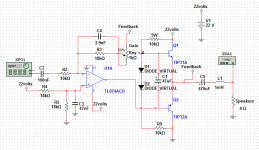
You can use this one, though it's not a power amp. Feel free to substitute output transistors and adjust resistors as required. This type of output buffer is called a "diamond buffer".
i couldn't understand how this works... this isn't really a power stage? what it does? how this works?
Greetings for all!
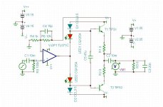
I'm here to show the fruits of some tries and disapointments. Follow above the schematic and a video about a amp that i could, finally, suceed and operate. But i've some problems with distortion on the high frequencies, and idk if its about the little speakers or about the circuit itself. The material is kind of self explanned... And i hope u guys could help me even more. Thanks.
Vídeo00031 - YouTube
Just very quickly...
Have you tried adding a zobel network to the output ? It sounds like the amp could be on the verge of instability. All you need is a 0.1uf cap and 10 ohm or thereabouts resistor and connected in series from the output to ground. The resistor must be non inductive so no wirewounds and the network connects from the amp output before your 470uf cap and coil.
Have you tried adding a zobel network to the output ? It sounds like the amp could be on the verge of instability. All you need is a 0.1uf cap and 10 ohm or thereabouts resistor and connected in series from the output to ground. The resistor must be non inductive so no wirewounds and the network connects from the amp output before your 470uf cap and coil.
Just very quickly...
Have you tried adding a zobel network to the output ? It sounds like the amp could be on the verge of instability. All you need is a 0.1uf cap and 10 ohm or thereabouts resistor and connected in series from the output to ground. The resistor must be non inductive so no wirewounds and the network connects from the amp output before your 470uf cap and coil.
I did this, but the cap(a poliester type) is making a awful noise, a REALLY awful noise.
Ok, updating... i put this after the inductor and notice no changes...
Last edited:
It does sound the amp is unstable.
Now there can be many reasons for this. As mentioned right at the start this kind of seemingly simple circuit is very non ideal in practice. The way it is wired up can be a major factor too, particularly where the speaker ground returns too.
Is the circuit exactly as in your latest diagram ?
Now there can be many reasons for this. As mentioned right at the start this kind of seemingly simple circuit is very non ideal in practice. The way it is wired up can be a major factor too, particularly where the speaker ground returns too.
Is the circuit exactly as in your latest diagram ?
C4 seems big at 3.9nF. I would have thought somewhere around around 47 to 100pf at most.
Also you could add an electrolytic across the two diodes to prove a low impedance path too AC. Something like 100uf although anything from 10uf up would help.
Dude, this tip about the cap between bases was THE TIP! Now this works like hell! HAHA Looks like the impedance of the diodes was screwing the sound... don't know.... What i know is that: Now works as supposed.
I'll post the results ASAP!
Hello Gentlemans!
Follows the schematic of the final circuit and a video demonstration of the loudness HAHA!
My First Super Simple Class AB Amplifier - YouTube
The Gain pot is 50k(B), Sry about that.
Follows the schematic of the final circuit and a video demonstration of the loudness HAHA!
My First Super Simple Class AB Amplifier - YouTube
The Gain pot is 50k(B), Sry about that.
Attachments
Last edited:
Pleased to hear you have it working.
Another point on your circuit. Putting the volume pot in the feedback loop isn't ideal for this application. It also has the problem of altering the "filter" time constants as the pot is altered (the 3.9nf cap + R). Normally best to run the amp at fixed gain and place the volume pot at the input (before the input coupling cap).
Any noises could well be down to layout and all that wiring
Ok guys, let's go then.
About C4 i've been doing some experiments with caps of 6pF and 560pF (those are the only i've avaliable here) and, of course, the 3n9 cap either. But something is funny about. The circuit only find stability when i put the cap between the 18k res and not between him and the pot, independent of the value. As i notice that, i go to the values.
The lower values deliver instability to the circuit, as the passive low pass with cap on the output that you guys suggested. What i did then? I keept the C4 configuration and, about the output i've put the 10R in parallel with the coil, making a LR low pass, and having no troubles with instability.
About input cap. As it gets bigger, for my surprise, i get more response on the bass. As gets lower, gets more response on trebles and high frequencies; What makes no sense to me.
So, about C2, i traded it for a 1uF cap and i'm getting a more hardcore bass, wich is pleasant, and the amplifier works as supposed to be.
One more thing... this pot isn't a volume pot, is a GAIN POT because i'm trying to figure the max gain capability without distortion that i can have with a PC signal input at max volume, ok?
Regards,
Me.
The input cap C2 forms a high pass filter with R2. So as you make C2 larger the lower frequencies are passed through more... just as you have found.
For a 10k (R2) you really need somthing like a 10uf cap (electroylitic is fine).
Not quite sure what you mean with C4.
Have you tried the C4 cap between pin 2 of opamp and point marked feedback on your diagram ? Use the 560pf cap to test. You could try adding a resistor in series with the cap, say 470ohm.
If you are testing the gain, set the pot to where you want, then remove pot and measure it's value and then use a fixed resistor of near that value for R3. So if pot were say 30K then use a 47K to replace R3 and the pot.
C4 Still remain between 18k resistor ONLY, and not between 18k AND the pot.
I'm doing some tests right now. I've found a 100pF Cap here. I'm testing C4 feedback with it.
So, the result is: when i put C4 between the two resistances(POT and 18k resistor), i got response on bass, but on high volumes he starts to give me some distortion
And when only between the 18K it's a lot worse.
And then i put the 560pF:
Between the two resistances, i got a good answer at max volume.
Between only 18k, distortion.
By hearing... as long as i raise the cap, i got more estability... i can guess that's because bigger values hold the gain when high frequencies appears on the output, holding some estabilization, but probably losing some hi freq response...
And, about the input. A cap impedance is inversaly proportional at the sound frequency. It's a series cap. when hi freq came, they pass more easily then low freq, wich should mean this is a "hi freq pass filter". But, how the hell, when i raise the value of a cap, i got more bass response? it should be opposite since the cap resist the low frequencies...
Last edited:
- Status
- This old topic is closed. If you want to reopen this topic, contact a moderator using the "Report Post" button.
- Home
- Amplifiers
- Solid State
- My First Super Simple Class AB Amplifier