Original source is here, just to make it clear that these are not my designs. Since i don't speak bulgarian, i can't ask anything about the design so its far easier to post it here. Quite fancy building this design as i've always fancied a quad. (did look at the 405 designs too) I am not certain whether I can substitute the 2SA1837 toshiba parts out for something like sanken 2SA1859A. It also suggests using ZTX552 for T5 which i can't find and ZTX752 for T6 which i've substituted for ZTX753. Are the MJL21194 main outputs the best or is there a better part. (the parts list i have differs from the parts on the schematic)
Last of all, the power supply design that i was intending to use was a 2x 50V 625VA toroid with 2 rectifiers filtered by 4 22,000uF caps. I noticed that the original 909 psu has some additional components and the +/- rails are offset. (+57.8V and -53.4V)
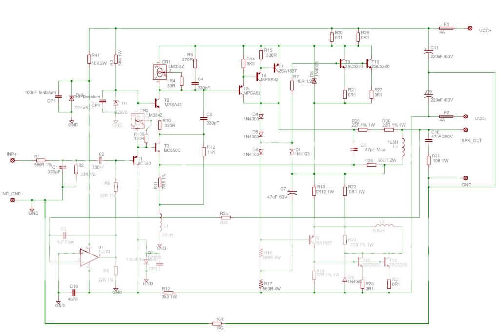
Schematic. I also have the Eagle design files with both schematic & pcb.
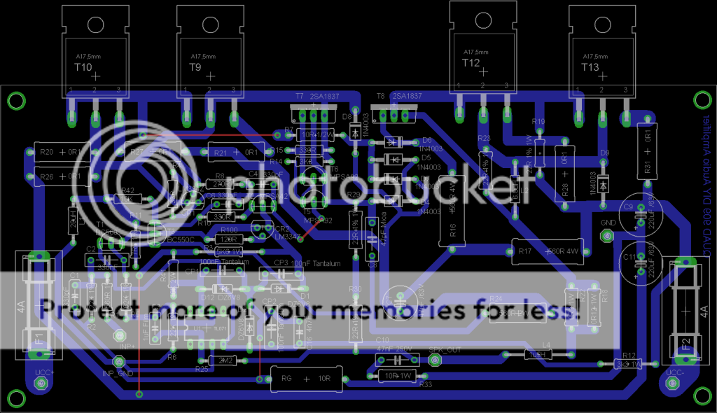
PCB
Last of all, the power supply design that i was intending to use was a 2x 50V 625VA toroid with 2 rectifiers filtered by 4 22,000uF caps. I noticed that the original 909 psu has some additional components and the +/- rails are offset. (+57.8V and -53.4V)
Schematic. I also have the Eagle design files with both schematic & pcb.
PCB
all is a about sonic signature
repairing an average of 400 amps per year from time to time i have been listening many opinions from many "experts" .
costumer of mine trashed a mimesis 9 Goldmund and replaced it with an ESP P3A ... what can you tell about that ? ( costumer is a university professor of physics has deep knowledge of sound at the age of 55 is what we call a sophisticated listener and obviously with a sophisticated set up )
If the electric setup is proper amplifier will work and produce sound ... now if the sonic signature will "fit" your ears is a different question.
Well I do speak bulgarian 🙂
Also I'm a member of this forum. They suggest replacing the ZTX parts with MPSA93 but is not that critical any device with close properties and enough sustaining voltage will fit here.
You can replace the 2SA1837 with MJE15031 or something different with similar characteristics. Overall selection of devices in this schematic is made according that what they can have and it is not absolutely critical. 2SA1859A should work fine I think.
In the forum have also a thread about Quad520 and they say that the slower MJL21194 performed better than the faster 2sc5200 but in this case I don't know.
If you have more questions ask here and I will ask in the bulgarian forum.
Last edited:
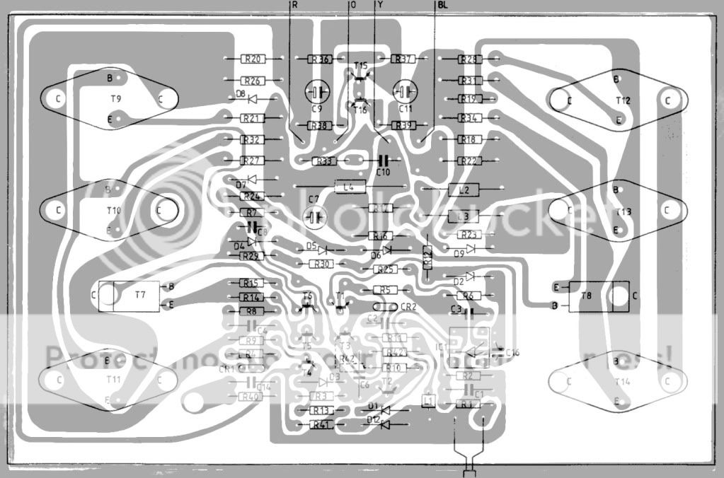
Thank you astankov much appreciated. Main question is about the power supply. (as i've not seen anyone listing any specifications for it) I've not bought anything yet as i want to make sure i get everything right first. The original design doesn't appear to have been cloned (R36-R39 and T15/16 are missing) Does this mean that the board is designed to run off an ordinary unregulated supply. The design i had drawn up was akin to this on the tnt audio site:
PSU4
PSU4
They claim that they using it with unregulated supply +/-50V. Also say that using the virtual ground makes sound worse since they tried it with Quad520 but they didn't tried it with this one. Just noticed because never read this tread - in the first post they say that changed the value of L2 to be able to work with faster devices like 2sc5200 otherwise amplifier is oscillating. So outputs need to be faster devices 2sc5200 or any modern fast power BJT.
Could someone explain,please,the rather unusual implementation of the quasi-complementary output stage?😕
Original source is here, just to make it clear that these are not my designs. Since i don't speak bulgarian, i can't ask anything about the design so its far easier to post it here. Quite fancy building this design as i've always fancied a quad. (did look at the 405 designs too) I am not certain whether I can substitute the 2SA1837 toshiba parts out for something like sanken 2SA1859A. It also suggests using ZTX552 for T5 which i can't find and ZTX752 for T6 which i've substituted for ZTX753. Are the MJL21194 main outputs the best or is there a better part. (the parts list i have differs from the parts on the schematic)
Last of all, the power supply design that i was intending to use was a 2x 50V 625VA toroid with 2 rectifiers filtered by 4 22,000uF caps. I noticed that the original 909 psu has some additional components and the +/- rails are offset. (+57.8V and -53.4V)
Schematic. I also have the Eagle design files with both schematic & pcb.
Is the schematic that you posted from the other site or did you redraw it?
Do you know if it is exactly as the real Quad is build, or did they substitute better/different transistors and such?
If you have any other documentation that would help also.
Here is the Quad 405 Service Manual it is quite similar and might answer some of your questions.
http://www.keith-snook.info/Schematics/QUAD 405 Service Data.pdf
I would guess that the higher V+ supply is needed because T5-T6-T7 have a high combined Vce
saturation voltage so the higher V+ voltage is needed to provide symetrical clipping. They could
have just had higher voltage to the drivers but then the outputs would go deeper into saturation
and they become very slow under such conditions - better for both to get the higher supply V.
The bootstrap on the negative side provides drive that is higher than the supply voltage so the
lower part of the output stage does not have the same problem.
Last edited:
Here are the BJT's i was looking at. (from other amp projects)
Sanken 2SC3263 (TO-3P)
ON Semi MJL3281AG (TO-264)
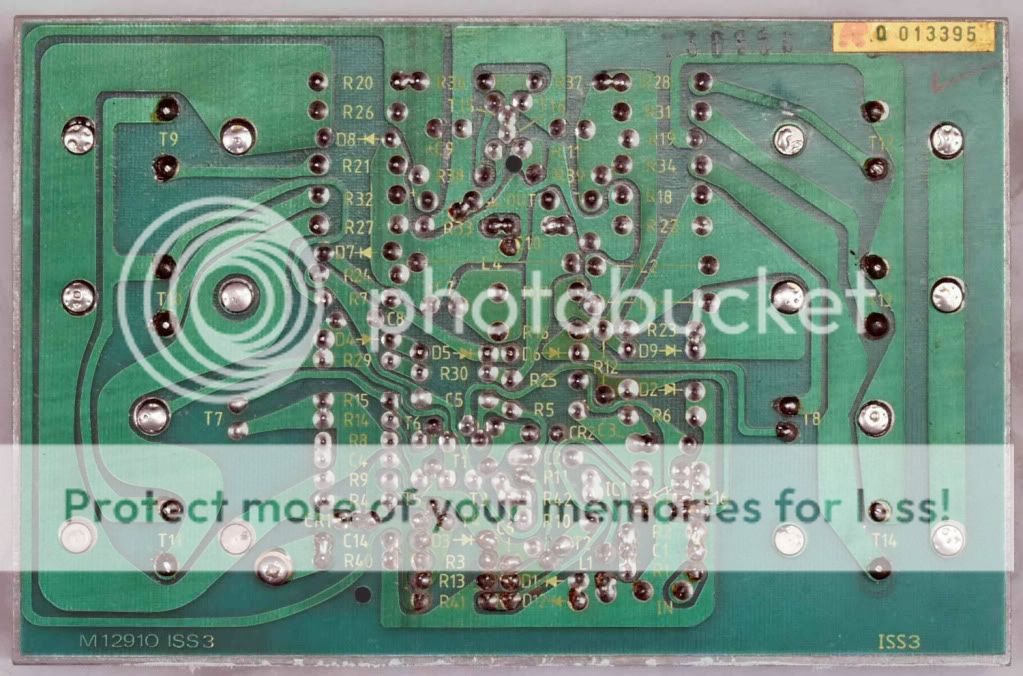
I have the service manual for both the 606 and the 909. I also have the original pcb layout for the 606 board M12910 issue 3, which uses 6 TO-3P devices. (i could post these if the board allows it)
The design in the OP is not completely identical to the original but extremely similar. The original has 6 large transistors vs the 4 in this design.
Sanken 2SC3263 (TO-3P)
ON Semi MJL3281AG (TO-264)
I have the service manual for both the 606 and the 909. I also have the original pcb layout for the 606 board M12910 issue 3, which uses 6 TO-3P devices. (i could post these if the board allows it)
The design in the OP is not completely identical to the original but extremely similar. The original has 6 large transistors vs the 4 in this design.
Could someone explain,please,the rather unusual implementation of the quasi-complementary output stage?😕
The simplest way to look at this is that it has a very high current class A VAS with a bias of about 50mA (-53V/1.12K). The bias is so high in this "VAS" that it is able to drive the top transistor directly (I'm not sure if it was a wise choice to leave out a driver transistor but there have been many revisions of the amp and none have had one) and also the output load through R29 and R30. When the drop across these resistors becomes large the output transistor turns on and acts as a current booster. The output stage is really a simple class B output stage with the addition of conceptually complex feedforward compensation to drive the distortion close to zero.
There are several papers providing analysis of the feedforward compensation with particular emphasis on the Quad design linked at the bottom of this page:
http://quad405.com/
Here is an AES paper on the subject:
http://quad405.com/jaes.pdf
Last edited:
Here are the BJT's i was looking at. (from other amp projects)
Sanken 2SC3263 (TO-3P)
ON Semi MJL3281AG (TO-264)
I have the service manual for both the 606 and the 909. I also have the original pcb layout for the 606 board M12910 issue 3, which uses 6 TO-3P devices. (i could post these if the board allows it)
The design in the OP is not completely identical to the original but extremely similar. The original has 6 large transistors vs the 4 in this design.
I'd like to know what all the original semiconductor types were if it is not too much trouble.
Thank you astankov much appreciated. Main question is about the power supply. (as i've not seen anyone listing any specifications for it) I've not bought anything yet as i want to make sure i get everything right first. The original design doesn't appear to have been cloned (R36-R39 and T15/16 are missing) Does this mean that the board is designed to run off an ordinary unregulated supply. The design i had drawn up was akin to this on the tnt audio site:
PSU4
What were T15/16 in the original design?
I have built 606 clone a few years ago. There are actually 6 o/p devices not just 4 as this redrawn schematic shows. It works fine with MJL21194 and BD244c driveres. And 606,707,909 are actually all the same circuit. This 4 transistor version is more like 520f.....If you want to clone it stick to the original values and components(tlc271, only one lm334 and j503....). Don't try to ,,improve it,,. Clone it because it works as it should.In case of oscillations add cc 1n cap across B-E at the negative current dumpers....
It is nice sounding amp.
Regards, Taj
It is nice sounding amp.
Regards, Taj
Here is the actual exact clone that i have been working on. (not quite perfect but very close i think)

Real board.
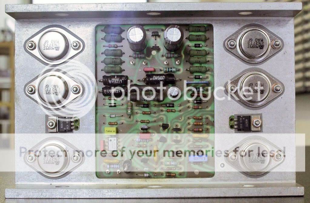
Real board.
Thank you Pete.
Sure, also, it is interesting that the negative half of the output stage is nearly identical to the early quasicomp designs. Nothing there makes it some sort of unique "current dumping" design. I think "current dumping" was a marketing idea to avoid the negative associations with a Class B output stage.
I'm not sure why they didn't make it fully comp the only good reason not to is that there are fewer different device types which is more costly from a manufacturing logistics standpoint. There is probably no performance gain going fully comp. A good reason to do it is to eliminate the inductor that is required to keep it stable.
It is very good to see that they tripled up on the output devices since it should easily drive 2 ohm loads.
Small snag i've hit whilst looking at the components. The part CR2 which is J503 diode current regulator doesn't seem to be available anywhere. (farnell list it as no longer stocked) It's a jfet with the gate connected to the source internally (from what i've found) Here is the datasheet. Closest i've found are some ATC E-102 but it is 1mA rather than 0.5mA.
Hi again.
If you need only 2 for stereo than you can get those from me.
I live in London now and my workshop is in Ljubljana so you have to wait till end of February when I plan to visit home. I can also bring it to U.K. if you can pick it up...
I also have some old version of Quad 520f schematic which don't have any current sources.....I mean everything is solved discrete. File is too big to attach so email me if interested.
Regards, Taj
I am not very familiar with the 606/909 Quad family, so these comments may not strictly apply here. But certainly in reference to the Quad 405 and even moreso with the Quad 303 the circuit is designed for extreme stability into a load. I always understood that the feedforward or reference to "current dumping" is in reference to this design and operational criteria.
The 303 was "unconditionally stable" and could drive a direct short indefinitely. I know this to be true because I've done it. The 405 is somewhat less stable but in comparison to other amps where a few miliseconds is all that's required, it's still remarkably so, rated for 5 minutes at full power into a direct short. Again, I've run the 405 with shorted outputs for brief periods and can report they work as normal once the output short is removed.
Power output falls as impedance falls (below 4~8 ohms) so that at zero load output is also zero.
I am not so well versed that I can read a schematic and say for sure what the design is doing, but I have used these amps and I can assure you the above is how they actually operate in the field. I have seen blown 405s but I've never known a 303 to need repair.
The 303 was designed to run the Quad ESL and to replace the vacuum tube 22 (mono) in the task. It's quite possible Peter Walker felt that extra caution was needed to protect both the speaker and the newfangled transistor amps.
The other somewhat unusual (although more common with British designs) design note is they are designed for full output with about 500 mV input. Care should be taken that any preamp or line level attenuator is sufficiently quiet for good performance. That there is no need for outputs nearer 1 or 2 V makes that somewhat simpler to achieve.
Last edited:
After a lot of hunting around i've found some suitable current regulator diodes at mouser. (1N5292 & Semitec E-501)
I've done a rough drawing of the half the amp in the modu 3u chassis. Design is to scale. PSU is 2x 300VA 40Vx2 transformers, a 400V 35A bridge, and 4 22,000uF 100V capacitors. (somehow cheaper than the 15,000, they are wrong in the drawing as they are 50mm dia and should be 65mm)
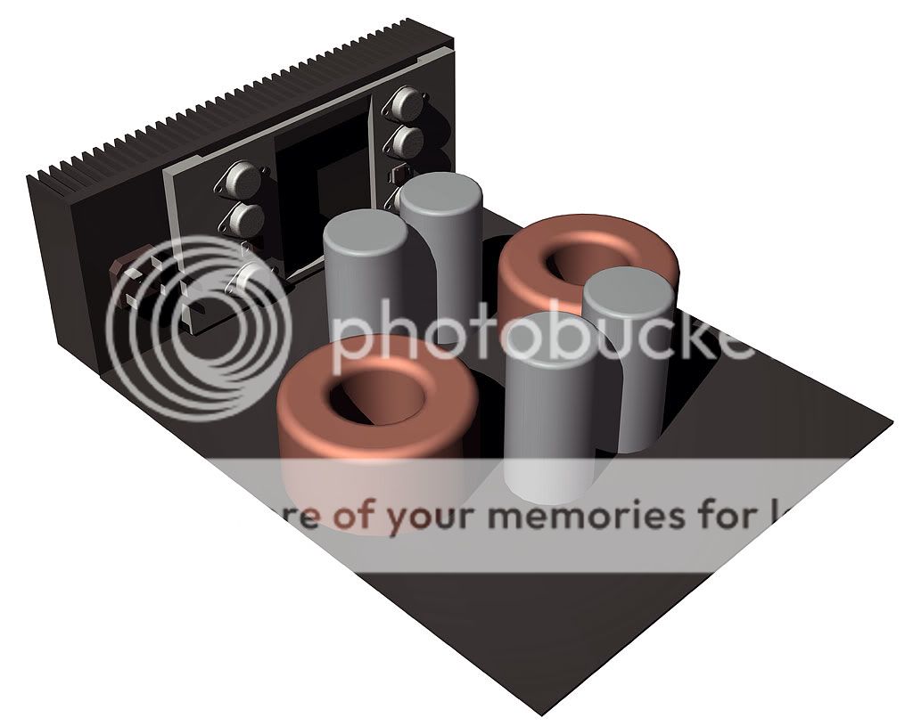
I've done a rough drawing of the half the amp in the modu 3u chassis. Design is to scale. PSU is 2x 300VA 40Vx2 transformers, a 400V 35A bridge, and 4 22,000uF 100V capacitors. (somehow cheaper than the 15,000, they are wrong in the drawing as they are 50mm dia and should be 65mm)
- Home
- Amplifiers
- Solid State
- QUAD 909 Clone