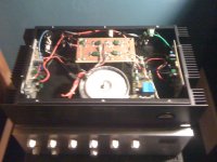
I have a ClarityCap on the RCA jack inputs and the NFB capacitor is 10uF to limit the bass to my speakers. I don't think that the decoupling capacitors have anything to do with it, the amp is not oscillating. I did have a problem with the amp oscillating at first until I changed the VAS transistor from BD13916 (HFe 100-250) to KSC3503D (HFe 60-120), do you think that the HFE classes of the transistors makes a difference.
The voltages at A is 35.4V, B is 34.1V, C is 12V, D is -35.4V, E is 34.2V
The voltages at A is 35.4V, B is 34.1V, C is 12V, D is -35.4V, E is 34.2V
Last edited:
I think there is something wrong with the amp.
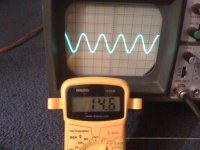
I connected the amp to a function generator and sent a 1KHz sine wave into it.
I connected an AC meter and oscilloscope to the amp output with NO LOAD and the max volts the amp will make before clipping is 14.9VAC on the meter with 700mv into it.
This is about 27Wrms into 8 ohms and 54W into 4 ohms, and is about 21Vpk which seems rather low given the supply rail.
Yes the hfe class of the transistor could make a difference..
I get all my transistors from fairchild and they let you decide the hfe grades can someone tell me what hfe grades should be used for this circuit. here are the data sheets.
http://www.fairchildsemi.com/ds/BD/BD139.pdf
http://www.fairchildsemi.com/ds/BD/BD140.pdf
http://www.fairchildsemi.com/ds/KS/KSC3503.pdf
http://www.fairchildsemi.com/ds/BD/BD139.pdf
http://www.fairchildsemi.com/ds/BD/BD140.pdf
http://www.fairchildsemi.com/ds/KS/KSC3503.pdf
Sorry, just saw the voltage readings...If these are under load conditions, i presume thats negative for(E is 34.2V) if so all fine. are you using scope to measure supply?
Dont worry about the cap values..the only cap thats going to affect clipping is the bootstrap C20. unless you have very thin wiring in the power lines
Dont worry about the cap values..the only cap thats going to affect clipping is the bootstrap C20. unless you have very thin wiring in the power lines
Clipping is symmetrical, I ment -34.2V, The circuit is build correctly because the PCB was designed using the same EAGLE file. Do you think that the low hfe of the vas causes the voltage not to be able to swing that high. Under heavy load the voltage of both rails only sags 4 volts.
Since DX usually only specifies standard (unclassified Hfe) semiconductors, it seems pointless to be more specific than to say "midrange" Hfe. Using highest grade as the displayed HX design shows will, as we find, run into excessive gain and oscillation problems whilst absolute low end Hfe parts may restrict gain too much. You should have no problems with BD139/40-10 for example.in any event.
The fact that you report a single, fixed maximum output voltage suggests something quite different to gain limitations however. There is an error here somewhere, whether the parts, board and schematic are fine or not.
Stereo has not been discussed. Is the second amp constructed and tested yet for comparison? If so, verify that the response is the same in both channels. Then you can be certain what problems are more likely. It should be possible to scope the VAS voltages at R15 and compare similar points at the bootstrap cap. and driver bases. Let's see if there are better clues available.")
The fact that you report a single, fixed maximum output voltage suggests something quite different to gain limitations however. There is an error here somewhere, whether the parts, board and schematic are fine or not.
Stereo has not been discussed. Is the second amp constructed and tested yet for comparison? If so, verify that the response is the same in both channels. Then you can be certain what problems are more likely. It should be possible to scope the VAS voltages at R15 and compare similar points at the bootstrap cap. and driver bases. Let's see if there are better clues available.
you have plenty of gain in the VAS already. lack of gain will cause lack of output, but clipping wont happen due to lack of hfe.
Are you sure its clipping ?/
the overall gain should give you about 19V for 700mV input. 15V isnt way off the mark here.
if you want more overall gain, reduce R20/R27 ratio.
Scope the base of T5. if its small clean waveform then amp is behaving properly.
If theres big spikes on it, compare them to output to see where the problem is.
thats RMS from the meter, also is your meter qualified to read AC at 1Khz ???I connected an AC meter and oscilloscope to the amp output with NO LOAD and the max volts the amp will make before clipping is 14.9VAC on the meter with 700mv into it.
soyyy i keep missing posts, I stayed up too late last year

I reckon some basic measurements to determine whether or not the correct biasing currents are set up in need here.
Measure the voltage drop across R18 and R19, check that they are almost identical and calculate the current that should be flowing through them.
Do the same for R22 and R23 and check once again that the voltages are balanced and that the current calculated is the same as the calculated current flowing through R18 and R19.
Next you want to measure the voltage across the two emitter resistors, R12 and R13. Check again that the voltage here is similar for both resistors and calculate the current that should be flowing. Unless this is a deliberately high bias AB amplifier the current should be around 75mA, or the voltage drop across either resistor being about 24mV.
If the current flowing through the Vbe multiplier and therefore the VAS is incorrect then this should show up as an issue with the biasing of the amplifier.
Do we really have a problem here? The multimeter will be reading in RMS, the first figure shows we've got 14.6Vrms which would = 40v p-p, or two divisions on the scope with the gain set to 20v per div. Which is what we see here.
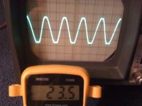
Increasing up to 23.5Vrms, gives us ~66V p-p or 33v per rail, which is just a couple of volts below the maximum rail voltage. This looks like you're getting clipping because you're hitting the ceiling that the rails can provide.
Can you double check to make sure that the readings are accurate? If so, switch down to around 60hz on the signal generator as the multimeter should be fairly accurate at this frequency.
Let's go off-track a bit:
Any problem is identical in both channels, so a systematic error if any.
C20 is only 10uF. Usually, with a low impedance like 10k or 12k as here and R27 around 500R, You need about 220uF as feedback capacitor to get low, undistorted bass here. It's not essential in all amplifiers like active crossover amps but I would think it noticeable driving average speakers.
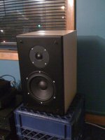
A 60Hz measurement may well be crazy in this light. Do you notice sound a bit weak in bass, even with your Polks, benproiii?
This doesn't affect the need to sort overall system gain out but at x30 in the amplifiers, it would seem an adequate gain setting for any application. Perhaps the Pass preamps unusual zero max. gain is just confusing what we might expect.
Any problem is identical in both channels, so a systematic error if any.
C20 is only 10uF. Usually, with a low impedance like 10k or 12k as here and R27 around 500R, You need about 220uF as feedback capacitor to get low, undistorted bass here. It's not essential in all amplifiers like active crossover amps but I would think it noticeable driving average speakers.
A 60Hz measurement may well be crazy in this light. Do you notice sound a bit weak in bass, even with your Polks, benproiii?
This doesn't affect the need to sort overall system gain out but at x30 in the amplifiers, it would seem an adequate gain setting for any application. Perhaps the Pass preamps unusual zero max. gain is just confusing what we might expect.
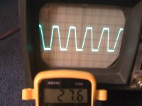
OK, so the amp's clipping at about +-30V as it should. No problem there. Dunno what's up with the meter, though. I suppose you could check your mains voltage with it and see if it gets that right.The scope is set to 20 v/div...
(Obligatory warning: Please try not to electrocute yourself)
Aha!!! If you build a second amp the same as the first, you can bridge them and get plenty of power.I have extra completed pcbs...
On an unrelated note, is the trace on your scope always that thick? If not, a thick furry trace like that can be a symptom of high frequency oscillation in the amp.
- Status
- This old topic is closed. If you want to reopen this topic, contact a moderator using the "Report Post" button.
- Home
- Amplifiers
- Solid State
- My amp is clipping with new speakers