Originally Posted by benproiii
does anybody know what the idle current should be it's at 43ma right now at 43V+/- should it be higher or lower than that.
This amplifier circuit design is under gone a few changes.. I would say mps42 are 300v types and there counter part is mpsa92's these are better than bc546's...
To bring down the bias voltage add a trim pot and this will improve the bias generator circuit and give more control so better adjustment can be made. you'll need to re-adjust a few time's as the heatsink temp will change. R2 remove and add a 220 or 120 ohm resistor plus a 1k trim pot in it's place.
Last edited:
Sorry, just saw the voltage readings...If these are under load conditions, i presume thats negative for(E is 34.2V) if so all fine. are you using scope to measure supply?
Dont worry about the cap values..the only cap thats going to affect clipping is the bootstrap C20. unless you have very thin wiring in the power lines
C13 is the bootstrap cap not C2o....this capacitor can be from 47uf to 330uf on some amp designs.. within the circuit's feedback network and with the resistor value's it has a volt gain of about 24..
Are you sure about this suggestion? See #76 - the OP tells us the amp is not far from oscillation with the stoppers fitted. Whatever typical amplifiers do or don't need for stability is irrelevant here without analysis or proof.relooking at the circuit scaled down circuit remove the the base stopper resistors to the o/p transistors and link wire across as these are not needed.. there's plenty of amplifier circuit's that work very well with out them.. check voltage's before and after..
Do you have any idea of the VA rating of the transformer, benproii?
As advised, above 40 volt rails and 4 ohms load, (quite likely with modern "8 ohms" design speakers) you approach SOA limits of single pair of output transistors. At 48 volts, you are permitting 100W/8R. You need 2 pairs for safe operation now or a small transformer whose voltage drops significantly under load.
The annoying news for you though, is that for all the power increase, you get very little more volume. This is not the solution.
Perhaps the amplifier piece responsible for the epic current leak will now get warm enough to discover the location of the current drop. With the new power resources, you should be able to discover your secret heater. That needs checked out to verify if the inbuilt current management is sturdy enough to continue working or if it may be expected to destroy speakers when it releases one rail.
Your amplifier is obviously sending a lot of power somewhere other than the speaker.
P.S.
I found authentic MJL21194 on sale, and they're not expensive at all. If you should happen to brace up the saggy rails, then you will need much more sturdy output devices because of far more current power, which is the force that operates speakers. And, I really wouldn't hesitate to add the protection of flyback diodes. Parallel output devices is worthy of consideration.
Last edited:
Thanks for that detail, benproii, the transformer is large enough to call a "stiff" supply for 2 unprotected 100W channels, so you cannot risk less than 2 pairs of output transistors. 
If you simply think because the Yamaha drove 5 channels safely that with just 2 channels it will still be safe, you have the idea backwards.
With no protection circuits, more load = lower voltage and less danger.
Logically, less channels = higher voltage and more danger
Some TO264 transistors certainly have higher SOA characteristics than others but if you consider them used on the same sink at the same supply and dissipation, there is not a lot of performance difference due to the restrictions of the package size/ heatsinking.
Next logical question: How much heatsink is available and is it a known rating like O.3 degrees C/watt?
Incidentally, that's a R.O.T. bare minimum in open air for what you'll need in summer for 2 x 100W channels. @25mA bias current/pair.
That is the logical conclusion from the above posts. If you want to continue with high voltage, you must provide a capable, safe source (output stage) for the attendant higher current. Transformer type is not critical but you need adequate power to cover the output current needs. Even Ohm's law will tell you that's how it goes. 
A rule of thumb says 80W 8R/Pair max. With VI limiters, SOA and more sophisticated limiting circuits, the power rating can be pushed significantly higher at some cost to sound quality. Like many modern audio "tricks", listeners don't usually notice the necessary compression, switching and distortion effects performed by the microprocessor, ICs or discrete devices involved.
If you go back to 42V rails, you are still on the edge of unsafety as previously advised, but acceptably so for average domestic use.
Destroyer X has rated his HRII design to use regulated (cap multiplier) voltage supply to the front end. This further limits the rail voltages and clipping point to safety at a volt or so less. This is sensible.")
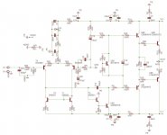
With bootstrap capacitor VAS designs, The VAS output voltage can well exceed the + power rail. This tells you that normal design rules need rethinking as VAS and output stages will be harder driven and clipped asymmetrically for the same general circuit conditions.
At the moment, your schematic shows a driver used as the VAS transistor which will work and be rugged but be slow and give higher distortion. Compare the characteristics with the original type KSC3503. You are looking for medium Hfe, high Ft and low Cob in this role. Minimal current is required at the operating voltage.
A rule of thumb says 80W 8R/Pair max. With VI limiters, SOA and more sophisticated limiting circuits, the power rating can be pushed significantly higher at some cost to sound quality. Like many modern audio "tricks", listeners don't usually notice the necessary compression, switching and distortion effects performed by the microprocessor, ICs or discrete devices involved.
If you go back to 42V rails, you are still on the edge of unsafety as previously advised, but acceptably so for average domestic use.
Destroyer X has rated his HRII design to use regulated (cap multiplier) voltage supply to the front end. This further limits the rail voltages and clipping point to safety at a volt or so less. This is sensible.
With bootstrap capacitor VAS designs, The VAS output voltage can well exceed the + power rail. This tells you that normal design rules need rethinking as VAS and output stages will be harder driven and clipped asymmetrically for the same general circuit conditions.
At the moment, your schematic shows a driver used as the VAS transistor which will work and be rugged but be slow and give higher distortion. Compare the characteristics with the original type KSC3503. You are looking for medium Hfe, high Ft and low Cob in this role. Minimal current is required at the operating voltage.
Last edited:
Are you sure about this suggestion? See #76 - the OP tells us the amp is not far from oscillation with the stoppers fitted. Whatever typical amplifiers do or don't need for stability is irrelevant here without analysis or proof.
over many years I've serviced plenty of high end pa amps such as peavey's/ qsc's and such like, the only one I recall was a EV P3000 amp that had many fault's..however it did have base stopper's of 2.2 ohms and was repaired to full working order with out them fitted.. any one who's worked on these tone weight amps will know how complex these amps are to set up!... with 20 o/p devices per block and two massive power supply's that will melt a heavy duty screw driver with easy...
Benproiii the good news here your amp is working and them voltages..it would be best to add a short circuit limiter that will pull back the driver currents to the o/p's transistor's..plus include a speaker fail safe the will act fast via disconnecting your speakers and stop them burning up...most dc detector circuits will act if the offset voltage is at 1 volt dc some many act on highter volts...triac trip's are not good..(know as crow bar systems) because not only do they shunt the whole o/p to deck but with knacker good o/p devices.. look at self's book or G Randy slone's book for such circuits..
relay speaker protection systems are a must in most systems...
relay speaker protection systems are a must in most systems...
With due respect for your successful repairs to commercial equipment, amptech, the intentionally wide stability margins and general ruggedness of those proven designs don't apply here. This is an "accidental" trial and error, simple domestic size one.
You can pull a lot of the safety measures on PA gear and they will work fine and sound better too - until you give them something they were designed to do - like cranking at full limiting into absurdly low, reactive loads.
Then you can tell us what the stupid little resistors were actually for.
You can pull a lot of the safety measures on PA gear and they will work fine and sound better too - until you give them something they were designed to do - like cranking at full limiting into absurdly low, reactive loads.
Then you can tell us what the stupid little resistors were actually for.
No problem. You have plenty of gain as you found with MPSA42/92. What was KSC 2690 Hfe anyway?I thought I could not use KSC3503 for VAS because I only have the D grade with an hfe from (60-120)
Last edited:
- Status
- This old topic is closed. If you want to reopen this topic, contact a moderator using the "Report Post" button.
- Home
- Amplifiers
- Solid State
- My amp is clipping with new speakers