Carlos, dear old friend,
the "DIY bacillus" infected me, since I have come to know you.
I am sure that you will remember my / EVETTE's versions (layouts) of your DX AMP, the DX BlameES/ST, the DX Blame MKII, ...
Mihai Rauta's "FC-100" inspired me once again to do a layout and group-buy of his AMP.
And - of course - this new AMP has to compete with your DX BlameES (this version, nothing else, that never made its way to the community, because it played like an "insane divine") ,with Michael Bittner's (my TO3) SYMASYM ...
I will give you the results of my "Shootout's Stammtisch" as soon as I will have them.
Best regards - Rudi_Ratlos
Last edited:
Rudi,
what results did you get that gave you reason to suspect that the devices are fakes?
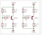
Your testing jig has quite high values of resistors for testing medium power devices say around 5W to 10W.
I suggest you reduce resistor values by a factor of 10, except emitter resistor, reduce this by a factor of 100 or even remove it.
Even for To92 devices, I would be reducing by a factor of at least 2 and ÷20 for the emitter resistor.
what results did you get that gave you reason to suspect that the devices are fakes?
Your testing jig has quite high values of resistors for testing medium power devices say around 5W to 10W.
I suggest you reduce resistor values by a factor of 10, except emitter resistor, reduce this by a factor of 100 or even remove it.
Even for To92 devices, I would be reducing by a factor of at least 2 and ÷20 for the emitter resistor.
Last edited:
Andrew, I will solder another test jig with reduced resistor values this afternoon and report the measurements.
I do not buy transistors from ebay!
I bought the 2SA1360 transistors from a German electronic distributor, who has a good reputation.
Best regards - Rudi_Ratlos
I do not buy transistors from ebay!
I bought the 2SA1360 transistors from a German electronic distributor, who has a good reputation.
Best regards - Rudi_Ratlos
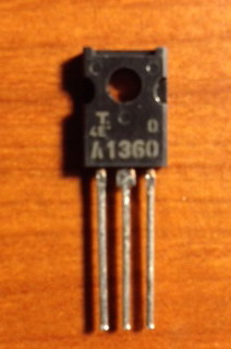
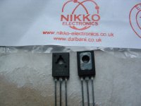
Andrew, I sent this picture
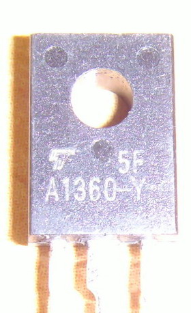
to Toshiba / Germany and asked them, if they can tell from the picture, if this is a genuine Toshiba transistor.
I received the answer a minute ago:
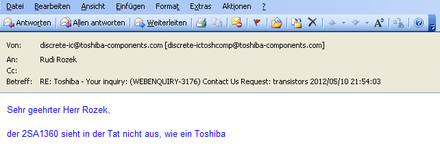
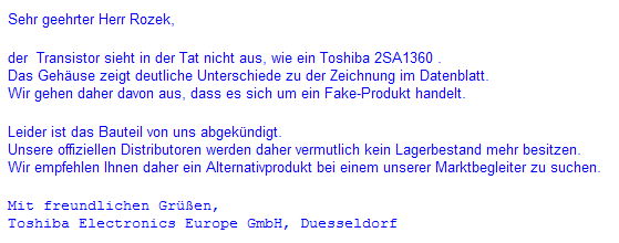
I translate: "The 2SA1360 does not really look like a Toshiba."
Best regards - Rudi_Ratlos
P.S. Lucylu: take care!
to Toshiba / Germany and asked them, if they can tell from the picture, if this is a genuine Toshiba transistor.
I received the answer a minute ago:
I translate: "The 2SA1360 does not really look like a Toshiba."
Best regards - Rudi_Ratlos
P.S. Lucylu: take care!
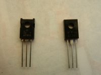
Started matching mine had to get more off ebay on left john
The one on the left looks ok I think.
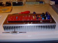
While I am waiting for replacement of the "fake Toshiba 2SA1360 transistors", I have started and prepared
the right side panel / heatsink of my FC-100's case.
I have been drilling holes and tapping them the whole day.
But the result looks perfect.
Best regards - Rudi_Ratlos
P.S. I did not pull the screws tight. There will not be an air-gap between heatsink and bottom plate, if I do.
the right side panel / heatsink of my FC-100's case.
I have been drilling holes and tapping them the whole day.
But the result looks perfect.
Best regards - Rudi_Ratlos
P.S. I did not pull the screws tight. There will not be an air-gap between heatsink and bottom plate, if I do.
Attachments
Last edited:
")

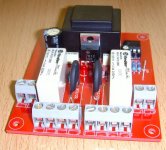
Great, Claus!
This is exactly the way the shunts and the soft-power-on shall look like!
I am currently thinking about using a 75W High-Voltage-Halogen light to delimit the inrush current
- instead of using 2 x NTC 22Ohm@25degree NTC resistors!.
Use any kind of "small" MKT and ceramic capacitors that you have at hand to "bypass" the 2.200µF reservoir caps of the shunts.
I am wishing you success with your build - please keep us (me) informed about your current progress - I love pictures - Rudi_Ratlos
Last edited:
Started matching mine had to get more off ebay on left john
I've got some with the package of the left side one, and the font of the right side one.
Has Toshiba ever changed the font?
Is the package on the left a genuine Toshiba, even though it has the correct package?
Pooge,
this one:
looks like an authentic Toshiba 2SA1360 transistor.
Not the one on the right side.
Best regards - Rudi_Ratlos
Yes, mine also have the package like that, but the font as shown on the right one of post 426.
Regarding your picture, the Toshiba "T" is not consistant with the "T" on most Toshibas I have seen. It doesn't look authentic. So having the correct package would not appear to guarantee authenticity.
- Status
- This old topic is closed. If you want to reopen this topic, contact a moderator using the "Report Post" button.
- Home
- Amplifiers
- Solid State
- Roender's FC-100 prototype and builder's thread