Sorry gentlemen, I cannot report any progress form my side.
On the one side I am still waiting for authentic Toshiba 2SA1360 and on the other side I have taken the side- and bottom - panels
of my ALU-case to an anodization company in Hamburg.
My FC-100 shall have a very nice ALU-case. It is worth it!
Best regards - Rudi_Ratlos
On the one side I am still waiting for authentic Toshiba 2SA1360 and on the other side I have taken the side- and bottom - panels
of my ALU-case to an anodization company in Hamburg.
My FC-100 shall have a very nice ALU-case. It is worth it!
Best regards - Rudi_Ratlos
Gentlemen,
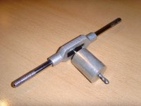
may I give you a "cheap trick", how to perfectly tap the holes of your heatsink / ALU-plate?
You will have to tap at least 21 holes to mount the FC-100 - PCB / transistors to your heatsink!
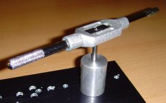
Go to your hardware store and buy a suitable "cylinder", made of wood, of steel, and drill a suitable hole through it.
You will then be sure that your "one-way tapper" will fit absolutely perpendicular into your heatsink.
Best regards - Rudi_Ratlos
may I give you a "cheap trick", how to perfectly tap the holes of your heatsink / ALU-plate?
You will have to tap at least 21 holes to mount the FC-100 - PCB / transistors to your heatsink!
Go to your hardware store and buy a suitable "cylinder", made of wood, of steel, and drill a suitable hole through it.
You will then be sure that your "one-way tapper" will fit absolutely perpendicular into your heatsink.
Best regards - Rudi_Ratlos
Attachments
Last edited:
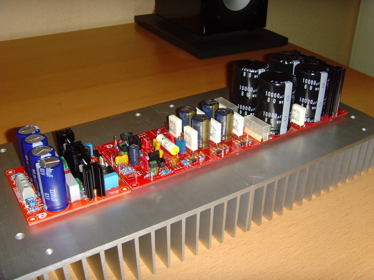
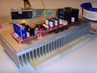
I have had 2 weeks of holidays and continued with the assembly of the FC-100 once I returned.
I picked up the bottom-plates from the anodizing company and fixed the heatsinks to it.
I applied a thin layer of thermal grease between the bottom plate and the heatsink.
I am still missing one component, the input- / de-coupling -capacitor: Vishay MKT1822, 2.2µF.
Everything else is done:

I think that I will be able to do the 1.st power on on Tuesday or Wednesday this week.
Is anybody else able to show a progress?
Best regards - Rudi_Ratlos
I picked up the bottom-plates from the anodizing company and fixed the heatsinks to it.
I applied a thin layer of thermal grease between the bottom plate and the heatsink.
I am still missing one component, the input- / de-coupling -capacitor: Vishay MKT1822, 2.2µF.
Everything else is done:
I think that I will be able to do the 1.st power on on Tuesday or Wednesday this week.
Is anybody else able to show a progress?
Best regards - Rudi_Ratlos
Attachments
") ,,,,,, lot of work to do to make this amp regards john
,,,,,, lot of work to do to make this amp regards john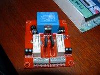
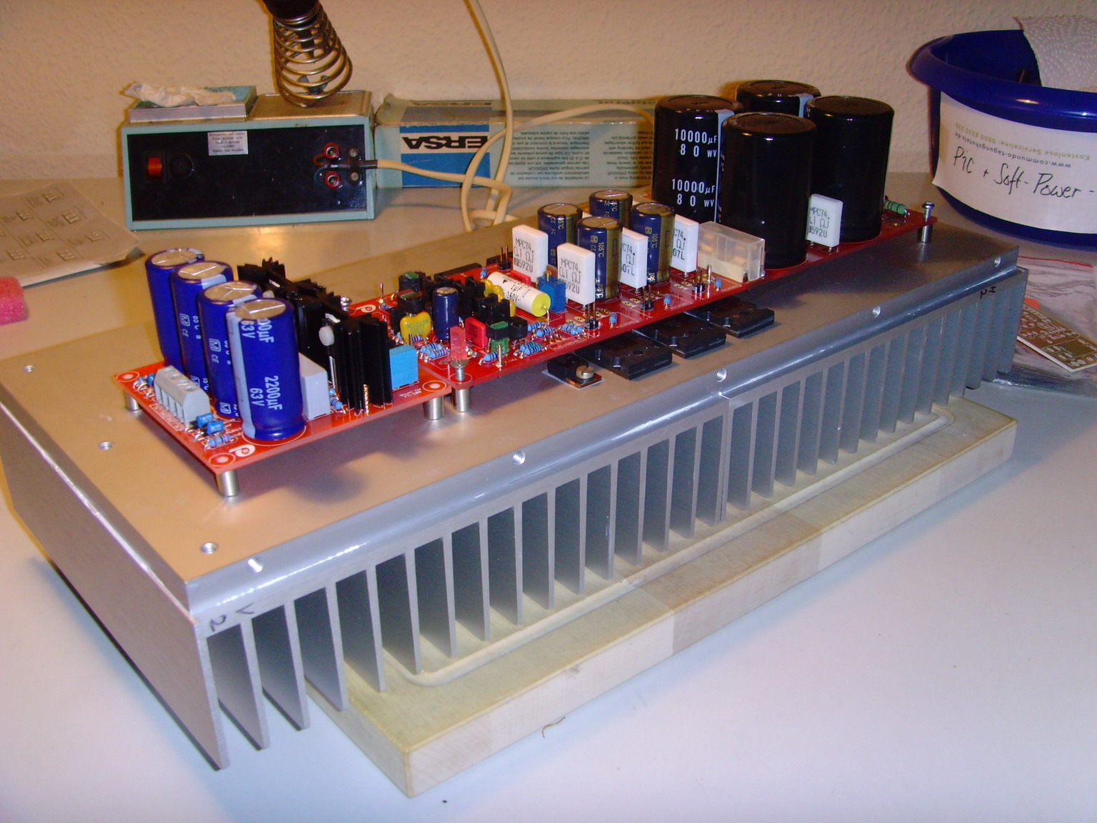
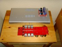
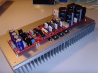
I completed the mechanical works today and attached the PCBs (Shunt PCB, AMP PCB and LSProtection PCB) to the heatsink.
As input- /decoupling capacitor I am using a Vishay MKT1822 / 2.2µF and bypass it by a Vishay MKP1837 / 10nF.
Tomorrow I will begin and test the components:
- the shunt (already done)
- the backend PSU (I will remove the fuses on the PCB before I start testing)
- the LSProtection PCB (new revision, for example: to support the AMPLIMO relay)
- the frontend-section (I will not apply power to the backend PSU for this test)
- the whole build
Keep your fingers crossed. I will report the results.
Best regards - Rudi_Ratlos
P.S. My heatsink is 380mm long and 170mm high.
Attachments
Last edited:
I did several tests regarding the frontend- (shunt) and backend-PSU of the FC-100: "they work as designed".
I tested my Rev.1 of the speaker-protection-circuit: it did not work.
This is the current hold, and I want to fix this issue, before I will go on with the FC-100.
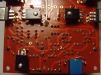
I designed the Rev.1 of the LSProt - PCB to support a "special audio relay" - the "AMPLIMO" (a 24VDC relay):
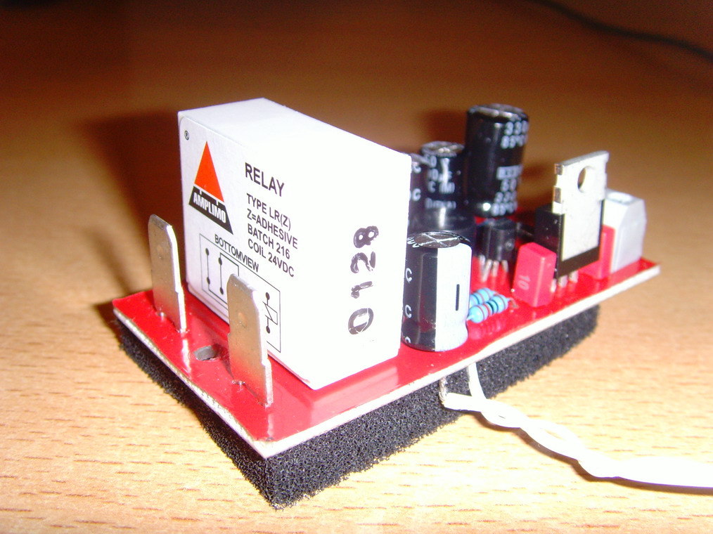
This relay has 2 contacts: a Wolfram-contact "for the rough" (is this understandable English?) and a Silver-contact for small currents:
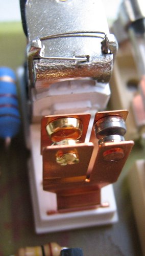
I measured the relay's coil resistance: 680 Ohm, and I was not able to get it working with a voltage of about 14V applied across it.
I will therefore have to revise the schematics shown above once more, but since I know that my DIY friend ZSOLT also wants
to use the AMPLIMO-relay, I am quite sure that together we will overcome this issue quite soon.
Best regards - Rudi_Ratlos
I tested my Rev.1 of the speaker-protection-circuit: it did not work.
This is the current hold, and I want to fix this issue, before I will go on with the FC-100.
I designed the Rev.1 of the LSProt - PCB to support a "special audio relay" - the "AMPLIMO" (a 24VDC relay):
This relay has 2 contacts: a Wolfram-contact "for the rough" (is this understandable English?) and a Silver-contact for small currents:
I measured the relay's coil resistance: 680 Ohm, and I was not able to get it working with a voltage of about 14V applied across it.
I will therefore have to revise the schematics shown above once more, but since I know that my DIY friend ZSOLT also wants
to use the AMPLIMO-relay, I am quite sure that together we will overcome this issue quite soon.
Best regards - Rudi_Ratlos
Last edited:
I can't read your pic.
Here's some guidance.
24V coil with a 680r resistance needs a nominal 35mA to pull in.
The Ic of the switching transistor should be assumed to be >=35mA.
That transistor must be operated saturated. This requires a base current of ~3.5mA.
The driver transistor must have an Ic equal to that 3.5mA when 24V is available to trigger the relay.
The impedance of the driver transistor circuit is Vdrop of Rc + Vce + Vbe*2.
I'll assume Vbe*2 ~=1.4V, Vce (not saturated) ~0.5V, Vsupply=24V.
Vdrop of Rc = 24-[1.4+0.5] =22.1V
Ic = 3.5mA
Rc = 22.1 / 0.0035 = 6k3. Use 5k6, or 6k2, or 6k8.
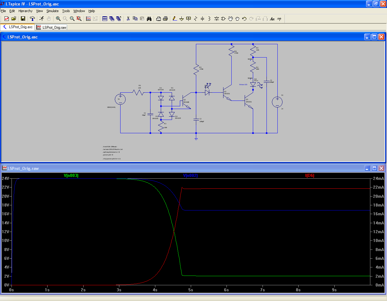
The "boost" capacitor taps across the relay coil and the switching transistor.
This capacitor will charge up fairly quickly to ~90% of Vsupply.
It will then partially discharge into the relay coil when the switching transistor triggers.
The relay will hold IN even when only 50% of the nominal current is available. You can use a dropping resistor of equal value to the coil when Vs=24V. You can increase the dropping resistor when Vs >>24V
Here's some guidance.
24V coil with a 680r resistance needs a nominal 35mA to pull in.
The Ic of the switching transistor should be assumed to be >=35mA.
That transistor must be operated saturated. This requires a base current of ~3.5mA.
The driver transistor must have an Ic equal to that 3.5mA when 24V is available to trigger the relay.
The impedance of the driver transistor circuit is Vdrop of Rc + Vce + Vbe*2.
I'll assume Vbe*2 ~=1.4V, Vce (not saturated) ~0.5V, Vsupply=24V.
Vdrop of Rc = 24-[1.4+0.5] =22.1V
Ic = 3.5mA
Rc = 22.1 / 0.0035 = 6k3. Use 5k6, or 6k2, or 6k8.
The "boost" capacitor taps across the relay coil and the switching transistor.
This capacitor will charge up fairly quickly to ~90% of Vsupply.
It will then partially discharge into the relay coil when the switching transistor triggers.
The relay will hold IN even when only 50% of the nominal current is available. You can use a dropping resistor of equal value to the coil when Vs=24V. You can increase the dropping resistor when Vs >>24V
I tested the FC-100 's frontend today.
I connected the frontend-PSU to the amplifier and left the backend-PSU unconnected.
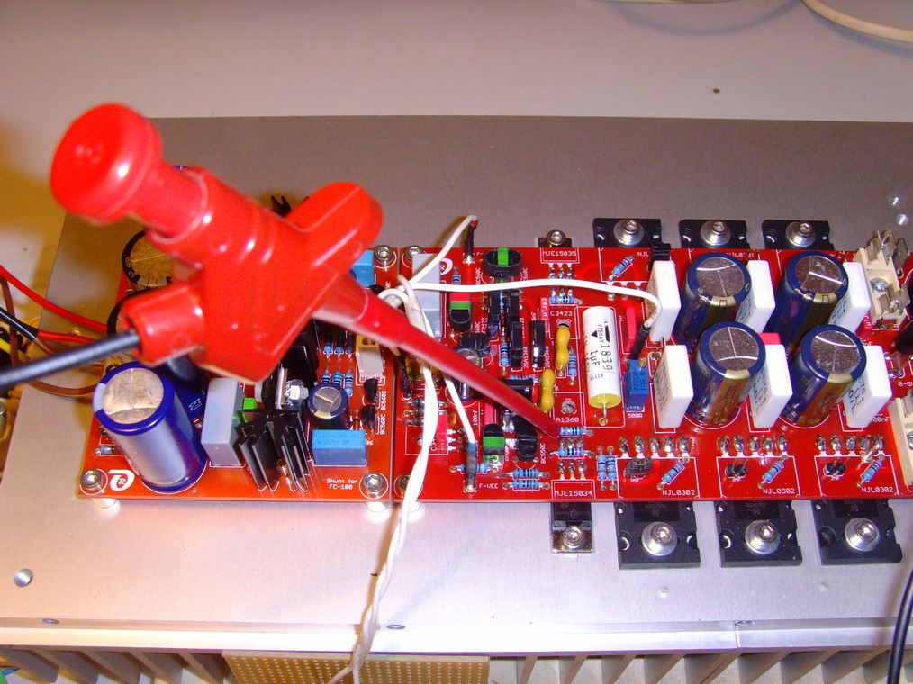
All LEDs are burning, no smoke signal, ...
I applied a 400 Hz sine-wave to the input and connected my scope to the negative pre-driver's base.
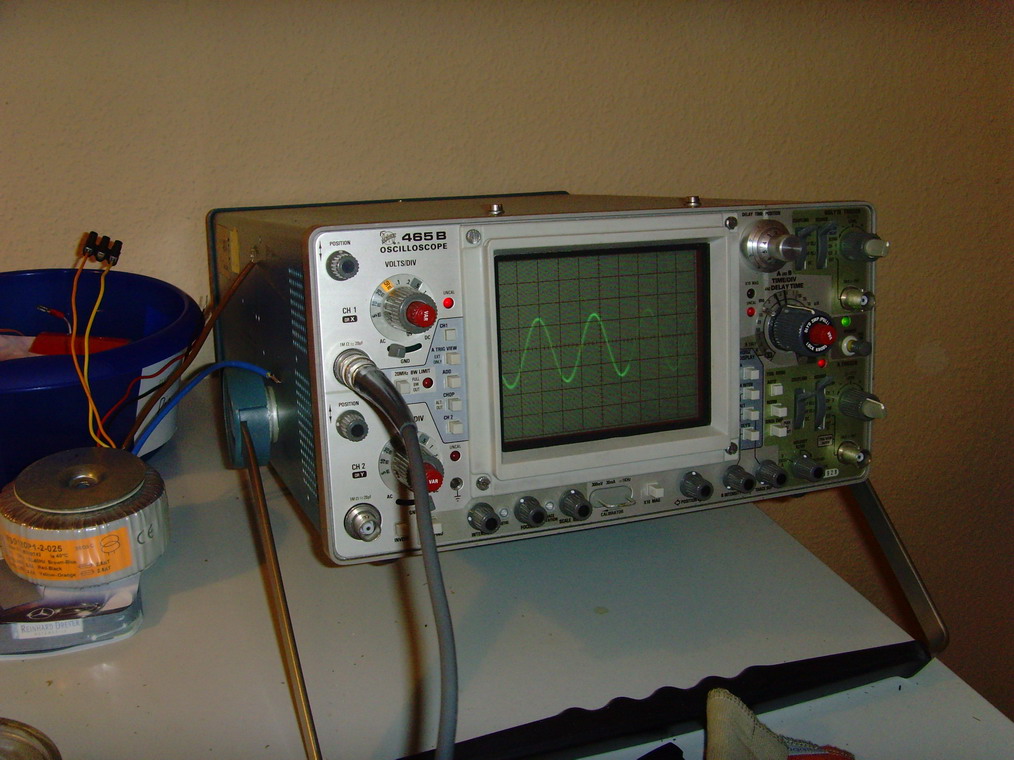
This looks perfect.
I will check the backend tomorrow, make sure that no pins of the drivers or output transistors have any resistance to the heatsink, ...
In the meanwhile I wait for the result of ZSAudio's test of the AMPLIMO relay.
ZSAudio has an adjustable PSU (I do not have) and will tell me, how the AMPLIMO works in real life,
so I am able to adjust my Rev.2 of the speaker protection PCB.
Best regards - Rudi_Ratlos
I connected the frontend-PSU to the amplifier and left the backend-PSU unconnected.
All LEDs are burning, no smoke signal, ...
I applied a 400 Hz sine-wave to the input and connected my scope to the negative pre-driver's base.
This looks perfect.
I will check the backend tomorrow, make sure that no pins of the drivers or output transistors have any resistance to the heatsink, ...
In the meanwhile I wait for the result of ZSAudio's test of the AMPLIMO relay.
ZSAudio has an adjustable PSU (I do not have) and will tell me, how the AMPLIMO works in real life,
so I am able to adjust my Rev.2 of the speaker protection PCB.
Best regards - Rudi_Ratlos
I finally fixed the "AMPLIMO-relay" issue.
Of course my problems had nothing to do with the relay itself.
The reason for them was that my EAGLE's components' library contains 2 versions of the 2N5551 transistor:
a TO92-CBE version (which is discontinued) and a TO92-EBC version (which is the current one).
I picked up the wrong CBE version inadvertently and used it in my layout.
@ZSOLT: you have to rotate the 2N5551 transistors on your PCB!
This is the resulting schematics:
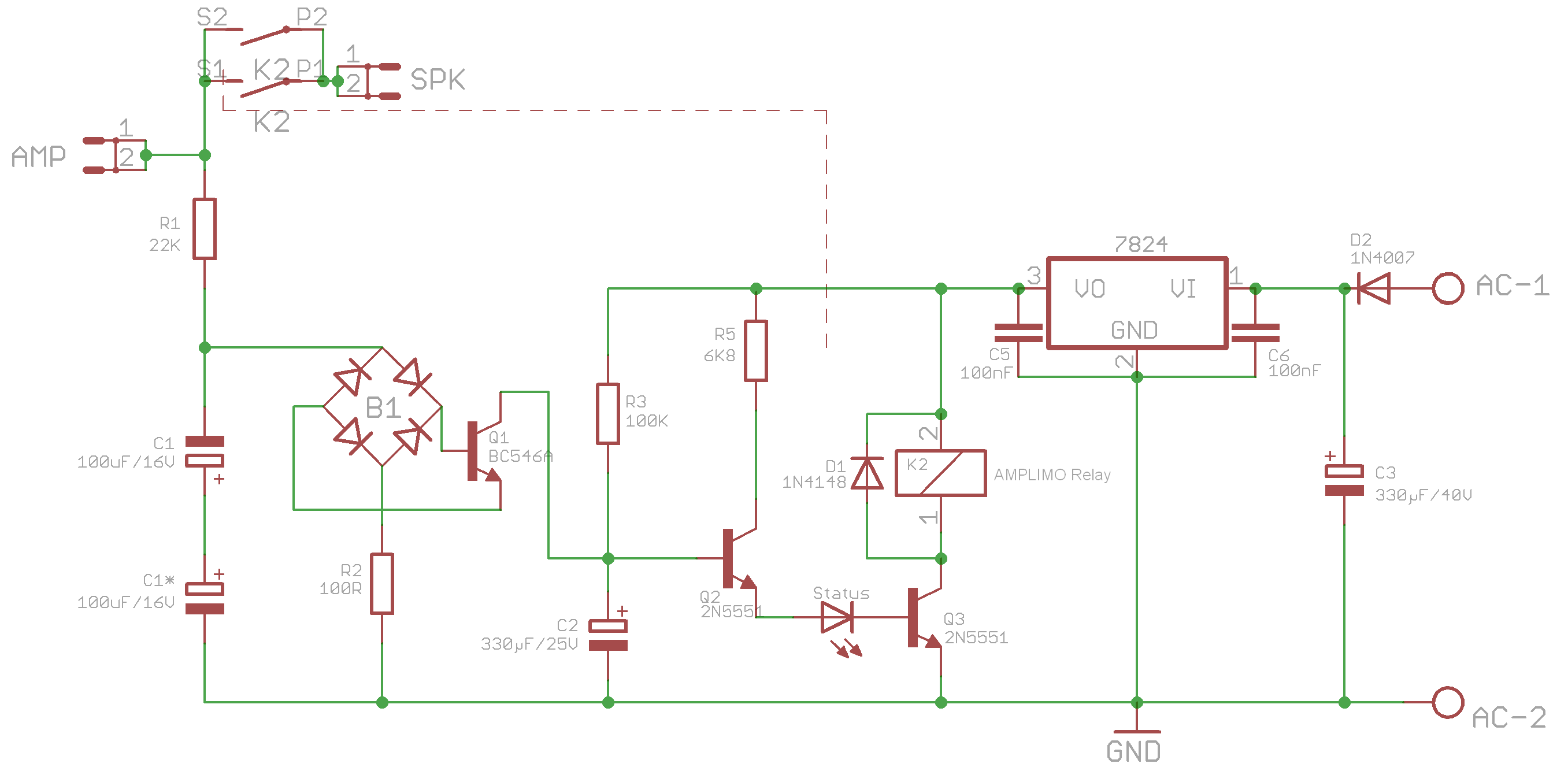
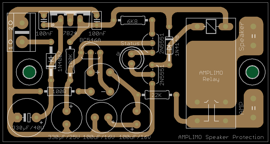
and layout:
I will now go on and finish the construction of the test-rig for my FC-100.
Best regards - Rudi_Ratlos
P.S. Thank you, Andrew, very much for your advise concerning the position of the LED.
The speaker-protection circuit nows works flawlessly.
Of course my problems had nothing to do with the relay itself.
The reason for them was that my EAGLE's components' library contains 2 versions of the 2N5551 transistor:
a TO92-CBE version (which is discontinued) and a TO92-EBC version (which is the current one).
I picked up the wrong CBE version inadvertently and used it in my layout.
@ZSOLT: you have to rotate the 2N5551 transistors on your PCB!
This is the resulting schematics:
and layout:
I will now go on and finish the construction of the test-rig for my FC-100.
An externally hosted image should be here but it was not working when we last tested it.
Best regards - Rudi_Ratlos
P.S. Thank you, Andrew, very much for your advise concerning the position of the LED.
The speaker-protection circuit nows works flawlessly.
- Status
- This old topic is closed. If you want to reopen this topic, contact a moderator using the "Report Post" button.
- Home
- Amplifiers
- Solid State
- Roender's FC-100 prototype and builder's thread