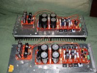
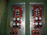
Yes i screw alu plate to heatsinks,my resistance reading are zero for all (fingers crossed i did that right) Photo for you Rudi.")
It cross my mind that the amp had ran for a very short time and both boards had same fault at same time that this was a component failure regards john
It cross my mind that the amp had ran for a very short time and both boards had same fault at same time that this was a component failure
regards johnAttachments
Why?The main common should be AC (not DC) connected to the heatsink/chassis. Something like a 1uF film cap.........
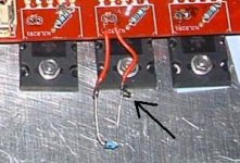
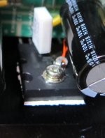
Dear oh dear; That diode is meant to be thermally bonded to the heatsink , not electrically connected. How did you manage to solder aluminium?
Are you sure you have enough screws to join the aluminium plate and the heatsinks? You have to have heatsink compound on the joined surfaces which I do not see. Maybe you did a very good job of removing the excess.
Sheldon's comment about connecting the input common the the chassis only via a film capacitor is particularly important if using NJL3281/1302 output devices. If using RCA input sockets the mounting hole(s) need to be oversize so that the outer shell does not contact the panel of its own accord or when a plug is inserted.
Keith
PS. The final remarks are relevant to connectors on a strip meant for mounting behind the panel. Other single connectors may have different insulating arrangements. The bottom line is that the outer shell needs to be insulated from the panel.
, not electrically connected. How did you manage to solder aluminium?Are you sure you have enough screws to join the aluminium plate and the heatsinks? You have to have heatsink compound on the joined surfaces which I do not see. Maybe you did a very good job of removing the excess.
Sheldon's comment about connecting the input common the the chassis only via a film capacitor is particularly important if using NJL3281/1302 output devices. If using RCA input sockets the mounting hole(s) need to be oversize so that the outer shell does not contact the panel of its own accord or when a plug is inserted.
Keith
PS. The final remarks are relevant to connectors on a strip meant for mounting behind the panel. Other single connectors may have different insulating arrangements. The bottom line is that the outer shell needs to be insulated from the panel.
Last edited:
Why?
http://www.diyaudio.com/forums/soli...age-audio-power-amplifier-79.html#post1805690
To follow the story, read from post 743 in the thread. Note post 783 as well.
Sheldon
Last edited:
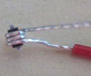
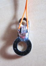
This is how I handle the external bias compensation diode (I used MBR0520L), first, use a wire and wound around the diode, then, soldered the body on a wire connection ring and mount on top of the transistor. The heat dissipated from the transistor will transfer to the diode effectively thru the mounting screw.
I have tested this method and it is very effective, I saw the bias start to raise but quickly corrected. It is able to maintain a constant bias current without thermal runway nor over compensated.
I have tested this method and it is very effective, I saw the bias start to raise but quickly corrected. It is able to maintain a constant bias current without thermal runway nor over compensated.
Yes Rudi soldered and checked with meter thanks john
Attachments
Thanks for help I will do that,,what I should have said now I have read Rudi s post again slowly is that the diode is soldered to the short wire each side ,not the sink ,I already said both sides have played music ,,now just fuse soon as I switch on ,I give in
Last edited:
Sheldon,
I am not sure what you are referring to.
It seems in my mind that there is confusion.
The Main Audio Ground MUST be connected to the Chassis via a wire (direct connection), or via a Disconnecting Network. Both MUST be able to pass Fault Current to PE.
That implies a DC connection from MAG to Chassis and a direct connection from Chassis to PE.
Does your AC connection comply with this?
Now to heatsink.
The heatsink is insulated from the output devices. It is electrically isolated until the builder decides to mount it.
It is usually bolted to the Chassis. That mounting is a direct connection. The heatsink unless specifically isolated becomes part of the Chassis.
However the length of the route from heatsink through the Chassis to the Disconnecting Network, or direct wire, to the MAG on to the amplifier power ground can and most probably is very long and must by the physical size of the loop include high inductance.
That high inductance will be high impedance at HF and very high impedance at VHF.
It is here that a heatsink to power ground capacitor could be of some help. A small VHF capacitor from heatsink to Power Ground could be helpful in avoiding parasitic effects.
I don't think your description matches what I have just described.
Would you care to explain your AC vs DC connection?
Last edited:
The Main Audio Ground MUST be connected to the Chassis via a wire (direct connection), or via a Disconnecting Network. Both MUST be able to pass Fault Current to PE. That implies a DC connection from MAG to Chassis and a direct connection from Chassis to PE.
Does your AC connection comply with this?
No.
Would you care to explain your AC vs DC connection?
The chassis is, of course earthed. The common is DC referenced via the input common to the preamp. The mains is isolated via the power transformer. I don't see the problem.
Sheldon
Andrew, Sheldon: your posts concerning MAG - to - Chassis connection is very interesting and informative, ..., but: will it help John to resolve his current problem?
As I understand John: both channels have worked, played music from a short while, but from the moment on, he connected his channels to his case (front and back-panel) the fuses blow.
There must be a short, somewhere. This is my opinion.
Best regards - Rudi
P.S.: The only GND (?) - connection that I am using in my build is: PE to chassis.
I don't care whether Sheldon's question is answered at this time.
What I care about are ambiguous statements that could be FATAL to other less well informed builders.
If in the meantime, I can help solve Sheldon's problem then great. But first, I consider that he starts with a safe build and then homes in on the problem.
What I care about are ambiguous statements that could be FATAL to other less well informed builders.
If in the meantime, I can help solve Sheldon's problem then great. But first, I consider that he starts with a safe build and then homes in on the problem.
I don't care whether Sheldon's question is answered at this time.
What I care about are ambiguous statements that could be FATAL to other less well informed builders.
If in the meantime, I can help solve Sheldon's problem then great. But first, I consider that he starts with a safe build and then homes in on the problem.
If there is a better solution than the one I used, then fine, I'm willing to adopt it. As to the chance of mains power contacting a circuit component, the chance is not zero, but not much more likely than the mains contacting the output of a double isolated build with no separate earth.
Sheldon
Last edited:
- Status
- This old topic is closed. If you want to reopen this topic, contact a moderator using the "Report Post" button.
- Home
- Amplifiers
- Solid State
- Roender's FC-100 prototype and builder's thread