hmm but the money you saved on fets you blew on solid gold heatsinks?
HA ha....gold...I wish.
BTW, the circuit drawn in Eagle has only 3 stages before the EC follower circuit, and this counts the DC servo that supplies the 'virtual gnd' for DC input bias. It looks complicated because there are two amplifier channels, the power supply, V-reg circuits for the amplifier front-ends, clipping detection, and DC detection/cut-off. Hopefully I can finish before the end of the year.
Last edited:
Are these packages really able to dissipated 1650 watts?
These are switching devices as well, but they appear to be of the Trench type structure. I'm not 100% on any 'new' age trench-fet but generally the trench type is susceptible to hot-spotting if used in a linear application. Sort of a secondary like breakdown effect. These may be different but >1600W is highly de-rated at high temp and continuous duty.
hehe yeah i figured as much, just having a laugh, not as funny when you have to explain it though......
when i saw the little sot-323 packages i initially thought they must be comparators , neat use of alternate devices, i always like to see that, as we in diyaudio can sometimes be a bit less than creative with parts choice. theres a whole world of fast, low noise and accurate smd devices that just need to find the right application and if we dont use them, often they will disappear when the technologies move on. ADSL drivers are a good example
when i saw the little sot-323 packages i initially thought they must be comparators , neat use of alternate devices, i always like to see that, as we in diyaudio can sometimes be a bit less than creative with parts choice. theres a whole world of fast, low noise and accurate smd devices that just need to find the right application and if we dont use them, often they will disappear when the technologies move on. ADSL drivers are a good example
SMD seems to be the new norm and the parts keep getting cheaper. Those little SMD metal film resistors are actually really good as far as noise, it's just that you have to watch de-rated Pd carefully. Sure I will use 0201 size resistors (0.6 X 0.3mm), great space savers, but only for a few mW and less than 20V. Soldering them is a different story, re-flow solder is one thing but it takes a steady hand to proto-type with them. Most of those in the above circuit is in the uW range. I use SOT-563 duels as well. SOT-963 is also available but at this time they cost more and the difference in space savings is small over the SOT-563. As for the SOT-923 Toshiba parts, that's just what they come in and I like those devices
 high linear gain but only 50mW Pd and that's before de-rating.
 In the power follower circuit above they bias constant 1mA @ ~6V.
My philosophy is that for a power amplifier, you don't need much current and power until the final stages. This opens up the door to lots of different parts that can be used.
 Most of those in the above circuit is in the uW range. I use SOT-563 duels as well. SOT-963 is also available but at this time they cost more and the difference in space savings is small over the SOT-563. As for the SOT-923 Toshiba parts, that's just what they come in and I like those devices
 In the power follower circuit above they bias constant 1mA @ ~6V.
My philosophy is that for a power amplifier, you don't need much current and power until the final stages.
I stick on hybride
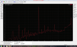
but with this fets, it will interesting, but now, I have did a measurement with 2sj/s2k lateral mosfets.
see the picture, everithing below fundamental is pc related, I don,t get that more flatten, see only the first couple of harmonics, higher she dissapear,, explane the warm sound of this amp, driver of the mosfets are CCS loaded cathode follower EL84 dc coupled to the mosfets with dc tracker for low offset measurement is for 12AU7 electro-harmonics tube preamp.
I search still for best measurement software, if you know a good one let me now, thanks.
Amp is without feedback, exept local, because a kathodefollower has 100 procent local feedback. Some people say that kathodefollowers are not sound friendly, is that so? I don,t try yet and so I am busy with plate follower and with feedback because of a lot more amplifiing.
Attachments
Voltage and Current on their own means nothing.
What you need to look at is the Safe Operating Area Rating (SOAR) of the devices.
This shows what the device can actually dissipate.
2000V transistors aren't new they have been used in TVs for years.
20A transistors aren't new either.
The problem is keeping that little slice of silicon below about 200 Degrees C.
Above that it just melts.
Voltage and Current on their own means nothing.
What you need to look at is the Safe Operating Area Rating (SOAR) of the devices.
This shows what the device can actually dissipate.
2000V transistors aren't new they have been used in TVs for years.
20A transistors aren't new either.
The problem is keeping that little slice of silicon below about 200 Degrees C.
Above that it just melts.
It is never that voltage/current leads to a very rugged device, always the designer has to look to specs, high voltage is on the other way save, it is a combination of them, low current high voltage and vica versa with respect to the max dissipation of a device. it is nice for the breakdown of a device to have high voltage capabilities.
tv stes has indeed high voltage and a couple of amps, like the BU series, but it was driven to 100 procent and so there was no dissipation,
sometimes the flyback was faulty and the drive to low, and she did blow up very easely because of to much dissipation when driven to soft.
Last edited:
It is never that voltage/current leads to a very rugged device, always the designer has to look to specs, high voltage is on the other way save, it is a combination of them, low current high voltage and vica versa with respect to the max dissipation of a device. it is nice for the breakdown of a device to have high voltage capabilities.
tv stes has indeed high voltage and a couple of amps, like the BU series, but it was driven to 100 procent and so there was no dissipation,
sometimes the flyback was faulty and the drive to low, and she did blow up very easely because of to much dissipation when driven to soft.
Exactly. Driven to 100%. This is where the SOAR is so important.
- Status
- This old topic is closed. If you want to reopen this topic, contact a moderator using the "Report Post" button.
- Home
- Amplifiers
- Solid State
- very heavy J-fet

