I found this!
little expensive but heavy 48 ampere 1200 volt j-fet.
http://semisouth.com/wp-content/uploads/2011/05/DS_SJDP120R045_rev1.3.pdf
high end audio
http://www.radiolocman.com/news/new.html?di=107175
little expensive but heavy 48 ampere 1200 volt j-fet.
http://semisouth.com/wp-content/uploads/2011/05/DS_SJDP120R045_rev1.3.pdf
high end audio
http://www.radiolocman.com/news/new.html?di=107175
Last edited:
Member
Joined 2009
Paid Member

Interesting. But expensive as new technology usually is. For now I will probably stick to my error correction vertical mosfet output stage. I used to be in the nice linear BJT camp but have discovered from experimentation and application that, IMO, despite being much simpler to use they are not the best output device. Perhaps in the end this technology will usher in an age of affordable and available power J-fets once again.") We can all only hope.
We can all only hope.
We can all only hope.SJDP120R045 - JFET
For those of us in the USA seems like Newark will carry them at $86 each. Not in stock yet but the link to order is;
SEMISOUTH|SJDP120R045|JFET, SILICON CARBIDE (SiC), N | Newark.com
For those of us in the USA seems like Newark will carry them at $86 each. Not in stock yet but the link to order is;
SEMISOUTH|SJDP120R045|JFET, SILICON CARBIDE (SiC), N | Newark.com
For those of us in the USA seems like Newark will carry them at $86 each. Not in stock yet but the link to order is;
SEMISOUTH|SJDP120R045|JFET, SILICON CARBIDE (SiC), N | Newark.com
this is the audio version SJEP120R100A 17 ampere, cost in holland 17.40 euros
and the audio version SJEP120R063A 30 ampere cost in holland 35.70 euros.
in fact these jfets are not real jfets because of the forwarded vgs, but some kind of enhanced, but with low on viltage of max 1.25 volt, so it seems a little bjt like voltages (twice as high at highest) so very interesting for testing.
Last edited:
you mean error correction like mine hybride, I have not build it yet, but without feeback distortion is very low.
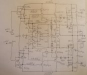
Similar. I use bootstrapping to eliminate the need for higher rails for the driving stage. Also faster RF transistors and a tight layout are used for the error amp and drivers. Since they have such little Vceo, 15V or so, cascode is a must. But this allows for the Pd to be spread out among multiple devices so I can use small signal stuff. One pair I like is the 2SC6026/2SA2154 from Toshiba. In this circuit they operate at a constant voltage and contant current. With Hfe ~300 they require a constant 3uA of base current from the VAS. This makes a nice load for a trans-impeadance, in the case below, complementary common gate J-fet VAS.
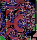
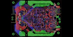
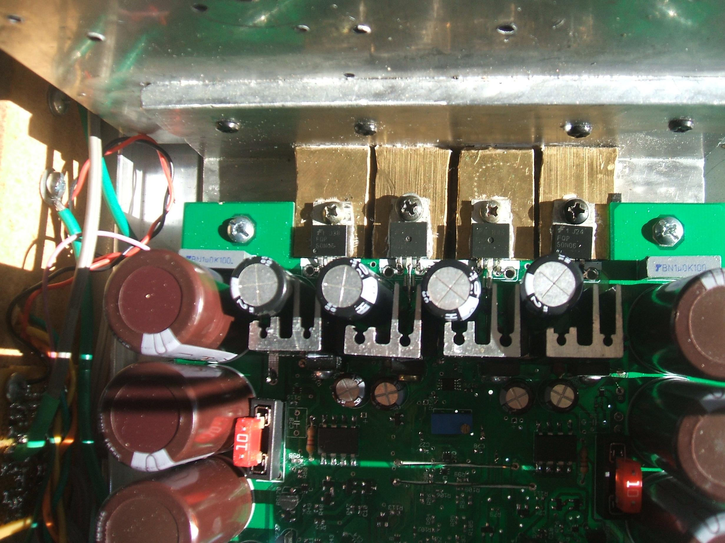
This is a new complete stereo project I'm working on. The transistors used for the error amplifiers are SOT-323 RF devices mounted underneath and in contact with the drain pin of the output devices for thermal feedback, similar to the previous amp project in the last picture. The next to last picture shows the whole PCB including daughter board cutouts. It's getting close to being finalized but I still have some detail and notation to add.
Thing is, in small quantities of 10, FQP47P06 costs $1.80. FQP50N06 is only 97 cents. Compared to the cost of those SIC devices, my money is on these.
Attachments

Last edited:
I must say you have made a very nice pcb with eagle, or maybe designspark software, do you now that software? it is completely free and now with a real simulation module.
I myself rae more a allfet or hybride type of designer, but your stuff looks very good, it looks a little complicated, try to use as little of components as you have shorter audio path.
Sorry of I am not so an calculate man, and don,t use fancy amp words, I am a little strange in combine ideas of amps, that is afcourse also nice to see, except my blown up part.
hmm but the money you saved on fets you blew on solid gold heatsinks?
hehehe there comes multisim in the picture, I get fake blews, however fets are strong as long you protect the gate with
zeners..
Are these packages really able to dissapaite 1650 watts?
- Status
- This old topic is closed. If you want to reopen this topic, contact a moderator using the "Report Post" button.
- Home
- Amplifiers
- Solid State
- very heavy J-fet