Hello all.
Hope this is the right forum. I am a desing engineer (mostly digital) and I have a problem with an audio circuitthat I kinda designed.
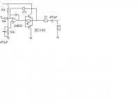
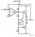
I have a bridge amplifier using BD139-16 and BD140-16 (see simplified rough pic).
It's part of a bigger system and we have made 50 of these. They were all kinda fine when testing the distortion with an AP (audio processor).
Now, another larger batch was made and ALL of them have huge distortion when testing on the AP.
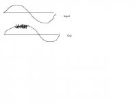
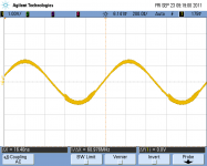
I looked into it today with a signal generator and oscilloscope and I found that the output stage (Headset load = ~100 Ohm) seems to burst into a VERY (YES VERY)!! high fequency oscillation at a certain level and fequency of input. I have attached a rough sketch of what I get on the scope. The osillation is visible in the top half of the output waveform.
I have tried everything I can think of and so has my collegue. We are not able to solve it at this stage and we are desperate.
The oscillation frequency is actually 69.65MHz (!!!!!!!)
It all occurs suddenly when the sine peak reaches around ~1V.
Removing the BD140 transitor solves the problem but then of course, I can't drive the full voltage swing required.
Removing the BD139 makes not much difference.
Touching anything (the op amp output etc) with a 10:1 scope probe, changes the output waveform and it changes the level at which the oscillations occurs.
Lowering the 47 R resistor by adding a 120R in parallel, stops the problem but again, does not allow for the full voltage swing, if lower impedance loads are used.
We have tried caps across the 27k, 47R, output to gnd (47nF gets rid of the HF part but then there is a step in the output waveform). we have also tried various other caps and ideas but nothing helps.
How the heck can such a circuit oscillate at 70MHz???? We suspect the LM833 and that it may not be suitable for a bridge amp like this but then what is the alternative in 8 pin smd?
The Vcc rail is +30V.
Maybe some op-amp / audio / analog expert out there can point me in the right direction?
Regards
B
Hope this is the right forum. I am a desing engineer (mostly digital) and I have a problem with an audio circuitthat I kinda designed.
I have a bridge amplifier using BD139-16 and BD140-16 (see simplified rough pic).
It's part of a bigger system and we have made 50 of these. They were all kinda fine when testing the distortion with an AP (audio processor).
Now, another larger batch was made and ALL of them have huge distortion when testing on the AP.
I looked into it today with a signal generator and oscilloscope and I found that the output stage (Headset load = ~100 Ohm) seems to burst into a VERY (YES VERY)!! high fequency oscillation at a certain level and fequency of input. I have attached a rough sketch of what I get on the scope. The osillation is visible in the top half of the output waveform.
I have tried everything I can think of and so has my collegue. We are not able to solve it at this stage and we are desperate.
The oscillation frequency is actually 69.65MHz (!!!!!!!)
It all occurs suddenly when the sine peak reaches around ~1V.
Removing the BD140 transitor solves the problem but then of course, I can't drive the full voltage swing required.
Removing the BD139 makes not much difference.
Touching anything (the op amp output etc) with a 10:1 scope probe, changes the output waveform and it changes the level at which the oscillations occurs.
Lowering the 47 R resistor by adding a 120R in parallel, stops the problem but again, does not allow for the full voltage swing, if lower impedance loads are used.
We have tried caps across the 27k, 47R, output to gnd (47nF gets rid of the HF part but then there is a step in the output waveform). we have also tried various other caps and ideas but nothing helps.
How the heck can such a circuit oscillate at 70MHz???? We suspect the LM833 and that it may not be suitable for a bridge amp like this but then what is the alternative in 8 pin smd?
The Vcc rail is +30V.
Maybe some op-amp / audio / analog expert out there can point me in the right direction?
Regards
B
Attachments
This looks like a rather crude amplifier!
First thing you should try is to put that integrating (compensating) capacitor to the full loop, i.e. attach the end it to the output (the common emitters) instead of to the output of the opamp.
You could also do a lot better in terms of the zero crossing distortion by adding and biasing the diodes and putting emitter degeneration resistors to the final transistors instead of in series to the output:
Good luck, Peter
Attachments
Last edited:

How the heck can such a circuit oscillate at 70MHz????
It's a long story, but the following might help:
An Oscillator is basically an Amplifier with "Positive Feedback", or regenerative feedback (in-phase) and one of the many problems in electronic circuit design is stopping amplifiers from oscillating while trying to get oscillators to oscillate. Oscillators work because they overcome the losses of their feedback resonator circuit either in the form of a capacitor, inductor or both in the same circuit by applying DC energy at the required frequency into this resonator circuit. In other words, an oscillator is a an amplifier which uses positive feedback that generates an output frequency without the use of an input signal. It is self sustaining.
Then an oscillator has a small signal feedback amplifier with an open-loop gain equal too or slightly greater than one for oscillations to start but to continue oscillations the average loop gain must return to unity. In addition to these reactive components, an amplifying device such as an Operational Amplifier or Bipolar Transistor is required. Unlike an amplifier there is no external AC input required to cause the Oscillator to work as the DC supply energy is converted by the oscillator into AC energy at the required frequency.
LC Oscillator Tutorial
Hello all,
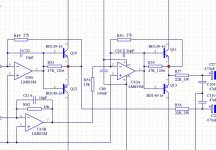
Don't shoot it down yet. I have attached the real schematic.
The crossover distortion is not bad as it is and the overall distortion is around 0.05% measured with the AP 70Hz- 10kHz (on the ones that do not have the problem).
I know about biasing and crossover distortion and I did originally have a current source bias network, similar to the ones you showed earlier. It worked fine but did not improve the overall quality/distortion enough to be worthwhile and thus we dunmped it again.
Please do not worry about the audio quality. It is actually quite good for this application.
I also cannot really change 100s of boards to a vastly different design right now.
The problem is the oscillations.
Did I mention 70MegaHz ? (Lower FM radio band)
None of the compnents (specially the LM833) should be capable to oscillate at such a high frequency but somehow they do.
I also know about Zobel networks and I made an attempt to add one as you can see from the 22R and 47n Restor /Cap on the output.
I have tried capacitors from emitter junction to input of opamp and NOTHING has made anyy difference.
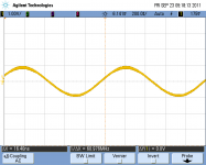
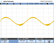
I have also attached some scope captures for you. you can see the sinewave output at a level just before the oscillation and then as soon as it is just increased, the oscillation is present on the peak of the sinewave. As the level is increased further, the oscillation spreads over the sinewave but eventually becomes invisible as the level gets more and more increased. The oscillation amplitude seems to remain constant.
Best regards
B
Don't shoot it down yet. I have attached the real schematic.
The crossover distortion is not bad as it is and the overall distortion is around 0.05% measured with the AP 70Hz- 10kHz (on the ones that do not have the problem).
I know about biasing and crossover distortion and I did originally have a current source bias network, similar to the ones you showed earlier. It worked fine but did not improve the overall quality/distortion enough to be worthwhile and thus we dunmped it again.
Please do not worry about the audio quality. It is actually quite good for this application.
I also cannot really change 100s of boards to a vastly different design right now.
The problem is the oscillations.
Did I mention 70MegaHz ? (Lower FM radio band)
None of the compnents (specially the LM833) should be capable to oscillate at such a high frequency but somehow they do.
I also know about Zobel networks and I made an attempt to add one as you can see from the 22R and 47n Restor /Cap on the output.
I have tried capacitors from emitter junction to input of opamp and NOTHING has made anyy difference.
I have also attached some scope captures for you. you can see the sinewave output at a level just before the oscillation and then as soon as it is just increased, the oscillation is present on the peak of the sinewave. As the level is increased further, the oscillation spreads over the sinewave but eventually becomes invisible as the level gets more and more increased. The oscillation amplitude seems to remain constant.
Best regards
B
Attachments
HEllo,
It has gone a bit quiet here
Update: Replacing the operational amplifier from National LM833 to OnSemi LM833 sorts out the problem. I have tried this in 20 units so far and it fixes it completely.
I have no idea why this is as I cannot see any real difference in the National and OnSemi datasheets.
Any ideas anyone?
Best regards
Bernt
The only that I see that may make a difference is that capacitors C23,C24 should be in parallel with the feedback resistors R49,R50 and not connected to the output of the opamp as this is not compensating for the extra gain stage of the transistors.
Also you should also have your bypass capacitors going from V+ and V- to ground and not just bridged across the supply.
I will take a closer look as somehow I believe I see an oscillator configuration somewhere the way it is displayed.
what happens if you increase the value of C23 and C24 aswell?
jer")
Also you should also have your bypass capacitors going from V+ and V- to ground and not just bridged across the supply.
I will take a closer look as somehow I believe I see an oscillator configuration somewhere the way it is displayed.
what happens if you increase the value of C23 and C24 aswell?
jer
The only that I see that may make a difference is that capacitors C23,C24 should be in parallel with the feedback resistors R49,R50 and not connected to the output of the opamp as this is not compensating for the extra gain stage of the transistors.
Also you should also have your bypass capacitors going from V+ and V- to ground and not just bridged across the supply.
I will take a closer look as somehow I believe I see an oscillator configuration somewhere the way it is displayed.
what happens if you increase the value of C23 and C24 aswell?
jer
Hello
I have tried a capacitor across R49 insead and it made no difference.
I have increased capacitor C23 up to 100pF and it made no difference. I have also removed capacitor C23 and it made not difference.
I have increased R53 to 120 Ohm and it stopped the HF oscillation but overall distotion is still 3%. If then, I swap to an OnSemi part, the distortion drops right back to ~0.05% in all instances.
Needless to say, this op amp has a bandwidth limit of 15MHz but the ocillations I see are at 70MHz.
This circtuit runs of a single supply with a half reference for the op amps and thus the decoupling capacitors are all going to ground.
Needless to say, I have tried various decoupling methods, all to no avail.
So far only the Op amp change works correctly.
Best regards
Bernt
Many Parts of the schematic is cut off so it is hard for me to tell exactly what is going on.
How ever it does not surprise me that switching to a different part works.
it has been a long long time since I have messed with the LM833, I am looking for my data on it,But I recall some thing about enclosing the input pins in a grounded ring in order to keep it from oscillating as they are very sensitive.
If I can still find that info I will post it for you.
jer
What Happens if you lift C109 and/or C110?
I once discoverd on oscilating opamp by grounding a capacitor and I believe it was on the output,But I can't remember, But I do remember that it was the lowest parts count oscilator that I have ever seen, one opamp a resistor and a capacitor I will dig through my files as think I had jotted it down somewhere too.
jer
c23,24 are best for stability right where they are – but only effective below the op amp GBW
if the oscillation is really at 70 MHz then the op amp doesn't directly control it - nothing is speced, controlled by the op amp manufacturer at that frequency - changing manufacturer is not a "robust" fix
the likely problem is wiring inductance, parasitic C forming a local single transistor RF oscillator when the current in the Q is high enough to push the ft beyond the trouble frequency
Zobel on the op amp output, damping the Q base circuit is an option but requires decent RF gnd/ps bypass - or you could double the Zobel with one between each base-collector
decent RF ps and gnd, bypass could help - "Zobel" style bypass/damper arrangements can be much better than the naive parallel decade caps advice you often see - high
Q ceramic or film caps can give impedance peaks in the ps rail with the lead, wiring inductance
series base "stopper" R of a few 10s of Ohms is another – just one in series with op amp output could be OK
it may be possible to find a lossy ferrite bead core that could be slipped over the output
Q base leads before assembly
all of these fixes want to be physically, electrically “local” to the output Q
you could also try replacing the output Q with slower devices
Last edited:
Hello all,
Sorry, the circuit is cut off. I can't show the whole circuit
The right side C27/C28 directly drive a 200 Ohm load, up to ~1Watt.
Both circuit halves behave identical and we can just concentrate on the left half for now. Bioth halves do NOT use the same pcb layout.
@geraldfryjr
Waveforms shown earlier, were taken with C109 / C110 removed.
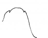
When fitted, the output waveform changes. the HF oscillation is then no longer visible but in its exact place, one can see a drop / step in the sinewave. (sort of like the attached sketch).
@jcx
I sort of agree but not fully (see last paragraph on reason).
It all points to an oscillation caused directly by the output stage transistor(s). More so, I removed the collector on the upper transistor and the problem continued.
I also removed the collector of the lower transistor and I still saw a very similar problem. When I completely removed the lower ransistor, the problem was gone. It appeared to me that the base / emiiter junction of the lower transitor has something to do with it. - Not 100% sure.
HOWEVER:
Also seperately interesting: I had the same op amp as a spare, in another part of this circuit. It was connected as a voltage follower with the input connected with a 22k resistor to Vcc/2. I measured a strong EMC/EMI radiation from that chip peaking at 110Mhz. I picked it up after we failed the EMC test and I measured it with a near field probe on the EMC analyzer.
I was never able to measure it with a scope as it simply disappeared whenever measured. The only solution there was to remove the resistor and replace it with a link directly to VCC/2. Again, no caps and nothing helped.
So we can't rule out the op amp itself completely in the above problem asI have seen something similar before.
Best regards
Bernt
Sorry, the circuit is cut off. I can't show the whole circuit
The right side C27/C28 directly drive a 200 Ohm load, up to ~1Watt.
Both circuit halves behave identical and we can just concentrate on the left half for now. Bioth halves do NOT use the same pcb layout.
@geraldfryjr
Waveforms shown earlier, were taken with C109 / C110 removed.
When fitted, the output waveform changes. the HF oscillation is then no longer visible but in its exact place, one can see a drop / step in the sinewave. (sort of like the attached sketch).
@jcx
I sort of agree but not fully (see last paragraph on reason).
It all points to an oscillation caused directly by the output stage transistor(s). More so, I removed the collector on the upper transistor and the problem continued.
I also removed the collector of the lower transistor and I still saw a very similar problem. When I completely removed the lower ransistor, the problem was gone. It appeared to me that the base / emiiter junction of the lower transitor has something to do with it. - Not 100% sure.
HOWEVER:
Also seperately interesting: I had the same op amp as a spare, in another part of this circuit. It was connected as a voltage follower with the input connected with a 22k resistor to Vcc/2. I measured a strong EMC/EMI radiation from that chip peaking at 110Mhz. I picked it up after we failed the EMC test and I measured it with a near field probe on the EMC analyzer.
I was never able to measure it with a scope as it simply disappeared whenever measured. The only solution there was to remove the resistor and replace it with a link directly to VCC/2. Again, no caps and nothing helped.
So we can't rule out the op amp itself completely in the above problem asI have seen something similar before.
Best regards
Bernt
Attachments
series base "stopper" R of a few 10s of Ohms is another – just one in series with op amp output could be OK
it may be possible to find a lossy ferrite bead core that could be slipped over the output
Q base leads before assembly
all of these fixes want to be physically, electrically “local” to the output Q
Forgot to add:
I have different models/ 2 types of this circuit and the pcb layout is completely different and the op amp feedback resistor in the other model are 10k instead of 27k. (gain = 1 instead of 2.7) Both versions have EXACTLY the same issue.
The actual layouts are relatively small as everything is smd so inductance and wiring, track crosstralk etc should not be an issue but perhaps the smallness contributes to this problem in a differnt way.
B
I haven't seen op amps oscillate at higher than their GBW - but it could be possible that the op amp's output Q have problems when combined with RF ps/gnd issues
supply, gnd bypass/damping, output series R or Zobel should help in that unlikely case
looking up the series: http://www.analogzone.com/acqt0814.pdf could be helpful
I wouldn't use the LM833 in any event - they were likely pushing the process capability before really good complementary/isolated processes matured
anything that can be driven to ordinary op amp ps/output V thru 22 Ohms in series per your schematic can be driven with some modern DSL driver op amps without external Q buffering - at low product volumes I don't count pennies (or even few $) in parts cost
Last edited:
Hello
One think I have noticed is that many people in the Audio fleld do not have the equipment to measure really HF oscillations. It may thus go unnoticed in some cases where it does not become part of the audio quality.
I used the NE5532 on an older version of this design and it worked very well. It can also drive more output.
I wasn't able to get it in smd at the time so I changed to the LM833.
I just noticed now that they do exit in SO8 and I will get some on order right away for testing. Thanks for remoinding me!
Best regards
Bernt
- Status
- This old topic is closed. If you want to reopen this topic, contact a moderator using the "Report Post" button.
- Home
- Amplifiers
- Solid State
- Bridge amp with LM833 and BD139/BD140 problems - please help.