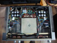
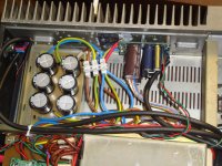
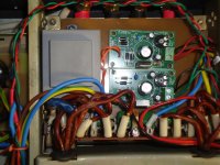
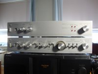
Here some pics of amp.
At the beginning i just wanted to get to life these old amps, they are both from mid80's. Really didn't have a glue that poweramp can make such a difference in sound. Tried the same setup at the beginning with different power amps incl the original one (one channel was still working). Sound was somewhat flat, lacking descent mid and low frequencies. I blamed speakers, the same age and origin than amps. But with thewire they are making descently good sound.
Preamp is pretty much original, changed only caps. Speakers, all elements are changed, mid and low to original ones, tweeters are Visaton DSM25FFL.
happy thewire amp owner


Great stuff!!!
I'm really liking the vintage amp restoration... I think that's three people who have done that now
I also like the awesome retro look of the amplifiers, especially the Cyrillic labels on the front!
It looks like a great implementation, and I'm sure it will provide you with plenty of listening enjoyment.
Thanks for posting the pics!
Cheers,
Owen
yeah I was going to mention that too, I guess its the tiny size, high performance and still being Class AB, so that existing power supplies can be used and the board is easily retrofitted into the chassis. Nice work kiwik! hopefuly i'll have some finished pics soon enough
thanks for warm words!
well, as said it was my first project of that size for decades. I had some doubts when received first kits of amps, that this is over my skills to do it. Managed still, with much of help from manual. Funny, i have done mistakes opc listed there again and again in the past. This time was lucky to avoid them.
With these amplifiers, soviets didn't hold back, at least in design, trying to build a hi-end amp. With preamp, volume control and tone controls are not variable resistors, but rotary switches. The same with poweramp attenuators. In the preamp design are visible signs to maintain hi-end level. well, end result wasn't that good..
Anyone having thewire kit and feeling they cannot finish it: yes you can. Just take your time, make a research of things you are not sure of; and doublecheck everything. This amp is worth to giving a try
wb Margus
Just ordered the bits I needed and will be up and running again... constantly on the lookout for a good used case with big(ish) heatsinks, but no luck so far. Might have to buy new yet...
Also working on an 8 Watt desktop amp inspired by Owen's LPUHP amp.
My last 4 resistors arrived today. Planning some time to test these amps over Easter and find some good bias resistor values for when I eventually build the switchable bias circuits.
I'm using one of these chassis - Design Build Listen Ltd
The case came with 2 x Conrad MF30-151.5 heatsinks which really need drilling soon.
I was also wondering if anyone had seen any recommended fuse values for the DPS600? I'm a bit puzzled about how to select fuse for my final build with 2 x dps600 and 2 x lpuhp all running through the same fuse.
I didnt think a fuse was needed for the dps600s, thought Roberto actually commented on this somewhere
Agreed! The DPS-600 has a built in button fuse on-board.
You only really need one for each of the two LPUHP amps, and for those you should look at roughly 250mA for 120V, or 125mA for 240V per amp. When multiple transformers are on the same 120v or 230V bus, I usually suggest separate fuses for each.
For the LPUHP you can probably cut a few traces and install an SMD fuse if you won't want an external one hanging off the board
Cheers,
Owen
Thanks guys!
Since I have the SumR tx for each LPUHP I'd rather go for an off-board fuse for each LPUHP rather than defile these PCBs. That all makes sense.
I probably need to work out my own fuse for all loads combined. I'm using FN9280-10-06 Schaffner EMC Inc | 817-1716-ND | DigiKey - 817-1716-ND as the IEC/switch for the enclosure and I need to work out a fuse for all loads combined. Discrimination of protection circuits for CB, main fuse and each individual load fuse is most certainly a case by case thing. I'll work it out in the morning, with a few less Peronis under my belt.
I'm mostly interested in what the inrush/startup current for DPS600 startup is at this point, I haven't found any info on that from Roberto.
Chris
Most line rectified SMPS have relatively low inrush current since they charge the primary and secondary caps in two stages.
As soon as you plug it in (or switch it on) you'll charge the HV bus with the primary side caps. This is probably a 360V bus so inrush current is pretty low.
Once the main bus is up past the UVLO threshold voltage, the switcher should kick on and charge the caps on the output rails, but this is often a soft start so as to not destroy the switching fets.
Either way, I'd guess the inrush is quite low, and you can always use the value from the existing fuse on the PCB.
Cheers,
Owen
Hi Owen,
Are there any kits left? If there are I would like two please.I am a bit late to this party an unfortunate accident having befallen my previous home made amps; I forgot to turn them off while working on my speaker crossovers with a grounded tip iron... The separate output and driver stage power supplies of 45v/56 v respectively and the heatsinks and cases can be reused in the event I can't fix them.
Regards,
Rob.
Hi Owen,
Are there any kits left? If there are I would like two please.I am a bit late to this party an unfortunate accident having befallen my previous home made amps; I forgot to turn them off while working on my speaker crossovers with a grounded tip iron... The separate output and driver stage power supplies of 45v/56 v respectively and the heatsinks and cases can be reused in the event I can't fix them.
Regards,
Rob.
Rob,
Bad news, unfortunately there are no kits left.
Chris
You could switch a relay between two different resistors, each fixed for a discrete bias level. Set one value for 200ma and the other for 600ma.
Regards,
Owen
Owen,
qusp and I have made some progress again in recent times on the switch-able bias option for these amps. We're now dangerously close to having something tangible. We've basically expanded on the above suggestion. 3 parallel resistors, one for ultra-low bias during to make the start up load lighter for faster starting of the DPS600. Second setting is for 'Summer'. Third for 'Winter'. Something like 100mA, 400mA, 600mA. Tiny SMT board is basically designed now after a little 'shoot out' between qusp and I to see who could make the smallest and neatest layout possible. (qusp currently has the best layout, unless I think up something).
Before we started on the layout stuff, I had selected these optically isolated relays and we've been working on the assumption they're suitable - IXYS CPC1117NTR
At the final hurdle, the question came from qusp 'does the bias relay's MOSFET bandwidth impact the LME chip?'
Now I'm reconsidering that assumption.
I'm scratching my head and I haven't been able to get my head around the bias circuit on page 4 of the LME49830 datasheet. Before qusp asked that question I had thought it was a simple DC CCS @2mA and voltage drop in resistors between those two pins gave us the bias voltage on the output, now it looks like I've potentially over simplified my idea on how the chip is operating.
Any comments on if the MOSFET in the relay above will have an impact on the amp performance?
Chris
Last edited:
yes the biasing arrangements with simple resistors (to suit laterals, no vbe multi needed) are not covered in detail other than saying its a simple ohms law calc. the lme is capable of a max 16v bias
as I understand it from a bit of rumination just now, its not the voltage drop, the 2ma constant current creates a bias voltage over the resistors between bias P and bias M pin, then this voltage creates a bias current over the 51R resistors driven by the Nout and Pout pins.
so with the 5k pot all the way up we get 10V bias creating 196ma over the 51R and thats our mosfet bias, so 392mA total bias. so to get 600ma we need 7.65KΩ giving 300ma bias to each fet
is that right?
also about the opto relay, its not just the bandwidth of the internal fets creating possible issues with the LME loop bandwidth, but also the capacitance of the fet relay, which can get as high as 15pf at ~10v output. now of course trimpots also have some parasitic cap, but it may be more linear.
it may not be such an issue due to not being in the FB loop proper, but I worried about it being effectively a parasitic/lumped compensation element. for the main setting there is no relay in the loop, so the main setting will be the most linear. I wonder if another form of relay is much better, unfortunately parasitic capacitance is not mentioned in many relay or trimpot datasheets
Last edited:
I think the best way to approach it is really going to be build and see. build with a trimpot soldered onto the adapter, start the amp and monitor the current, then remove the pot (or entire adapter) and measure it, then set the other desired points and measure them. then just generate these values by the parallel resistors. we can only calculate so far based on datasheet transfer character and LME drive current and values would need tweaking to match that in reality anyway.
pay no attention to my confused bias current calc above
pay no attention to my confused bias current calc above
- Home
- Amplifiers
- Solid State
- "The Wire AMP" Class A/AB Power Amplifier based on the LME49830 with Lateral Mosfets