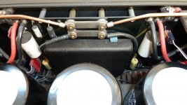
After a mishap with one of the potted modules of my Model 7 i got curious and took a peek inside. Always wondered why it sounded dull and attributed this to filter caps, passive components and execution. After all, based on this very useful post of BrianEno http://www.diyaudio.com/forums/pass-labs/186060-threshold-sa-4e-vs-sa-1-a.html#post2547185 and the quote from the Model 7 user's manual "Lack of overall or nested negative feedback eliminates time domain distortion" made me think that conceptually at least, this amplifier was indeed excellent.
Output stage is identical to the Threshold Stasis amps where it is similarly not within a NFB loop. John Curl once mentioned being a consultant for the early JRDG amps and this meshed well with the Mk2 input schematic shown in BrianEno's post above. Can you possibly combine Curl and Pass and not achieve greatness?")
A bit of historical background may be useful here. The Model 7 was initially produced in non-clandestine fashion. Eventually a Mk3 with an epoxied front end was introduced, followed by a "transimpedance" upgrade module which allowed Mk3 owners to obtain an even better performance. My set of Mk3 amps came with the "transimpedance" module installed.
So, after a bit of digging through some of the hardest epoxy known to man i came up with a circuit diagram. It may not be 100% correct as the reverse engineering exercise was a bit messy but the results are, nevertheless, interesting.
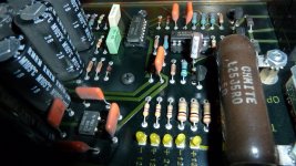
To begin with, there are two medium quality double opamps per channel which serve as balanced to single ended convertor, allow adjustable voltage gain, output dc servo and provide the important low impedance drive for the transimpedance section. I find this quite amusing. A high end manufacturer seems to have more scorn for audiophiles and their hearing than even hard core objectivists. So, the signal has passed through hundreds of opamps, what can another three do?
Adding further insult is the power supply arrangement for the opamps: 400uf per rail followed by a pair of 12v zeners, followed by about a foot of wire. No local decoupling of any sort that i could find. Imagine the poor audiophiles trying to find a matching zero NFb preamp for their Rowlands. The travesty of the high end.
And then there is the actual power amp. Unlike Rowland's claims it is quite the opposite of feedback free. It has, however, a rather interesting circuit. I certainly do not understand it completely and fail to translate it to standard topologies. The output, biasing, servo and input stages are clear but i really get lost with the workings of the current mirrors. If anyone feels up to analysing this ciruit it will really be appreciated. The front end seems a bit similar to the Chinese Model 9 clone circuit which i am not even sure is entirely correct http://www.diyaudio.com/forums/solid-state/50083-jeff-rowland-model-9-amp-schematic-really.html
I simmed both Mk2 and Mk3. Unsurprisingly, most of the distortion is generated in the output stage. It seems excessive, so maybe something is not quite right with my sims. The "stasis" pair is certainly the most critical part of the design. I couldn't find models for the 2SA1073/2SC2523 originally used and replaced them with 2SC2922/2SA1216 which should be at least as good. The servo is omitted for simplicity but would normally connect to the grounded side of R36 on Mk3 and R41 on Mk2.
As much as i like the Mk2 curcuit, transistor matching and precise setting of the input current sources is probably not easy. Could it be the reason JRDG quietly abandoned this circuit?
R35/R37 in the transimpedance sim were actually inductors. Forgot to measure them.
Eventually, i will probably build several front ends while retaining the Threshold output stage. Maybe a Threshold, a Mk2 and a Mk3 but with proper opamps, properly powered. Looking at the really high distortion at output i am not so convinced it is a great idea, but converting to a standard emitter follower output stage under a feedback loop may just be too hard for me.
I hope these circuits are of some interest to others as well. Any suggestions, corrections and modifications are most welcome.
Output stage is identical to the Threshold Stasis amps where it is similarly not within a NFB loop. John Curl once mentioned being a consultant for the early JRDG amps and this meshed well with the Mk2 input schematic shown in BrianEno's post above. Can you possibly combine Curl and Pass and not achieve greatness?
A bit of historical background may be useful here. The Model 7 was initially produced in non-clandestine fashion. Eventually a Mk3 with an epoxied front end was introduced, followed by a "transimpedance" upgrade module which allowed Mk3 owners to obtain an even better performance. My set of Mk3 amps came with the "transimpedance" module installed.
So, after a bit of digging through some of the hardest epoxy known to man i came up with a circuit diagram. It may not be 100% correct as the reverse engineering exercise was a bit messy but the results are, nevertheless, interesting.
To begin with, there are two medium quality double opamps per channel which serve as balanced to single ended convertor, allow adjustable voltage gain, output dc servo and provide the important low impedance drive for the transimpedance section. I find this quite amusing. A high end manufacturer seems to have more scorn for audiophiles and their hearing than even hard core objectivists. So, the signal has passed through hundreds of opamps, what can another three do?
Adding further insult is the power supply arrangement for the opamps: 400uf per rail followed by a pair of 12v zeners, followed by about a foot of wire. No local decoupling of any sort that i could find. Imagine the poor audiophiles trying to find a matching zero NFb preamp for their Rowlands. The travesty of the high end.
And then there is the actual power amp. Unlike Rowland's claims it is quite the opposite of feedback free. It has, however, a rather interesting circuit. I certainly do not understand it completely and fail to translate it to standard topologies. The output, biasing, servo and input stages are clear but i really get lost with the workings of the current mirrors. If anyone feels up to analysing this ciruit it will really be appreciated. The front end seems a bit similar to the Chinese Model 9 clone circuit which i am not even sure is entirely correct http://www.diyaudio.com/forums/solid-state/50083-jeff-rowland-model-9-amp-schematic-really.html
I simmed both Mk2 and Mk3. Unsurprisingly, most of the distortion is generated in the output stage. It seems excessive, so maybe something is not quite right with my sims. The "stasis" pair is certainly the most critical part of the design. I couldn't find models for the 2SA1073/2SC2523 originally used and replaced them with 2SC2922/2SA1216 which should be at least as good. The servo is omitted for simplicity but would normally connect to the grounded side of R36 on Mk3 and R41 on Mk2.
As much as i like the Mk2 curcuit, transistor matching and precise setting of the input current sources is probably not easy. Could it be the reason JRDG quietly abandoned this circuit?
R35/R37 in the transimpedance sim were actually inductors. Forgot to measure them.
Eventually, i will probably build several front ends while retaining the Threshold output stage. Maybe a Threshold, a Mk2 and a Mk3 but with proper opamps, properly powered. Looking at the really high distortion at output i am not so convinced it is a great idea, but converting to a standard emitter follower output stage under a feedback loop may just be too hard for me.
I hope these circuits are of some interest to others as well. Any suggestions, corrections and modifications are most welcome.
Attachments
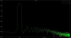
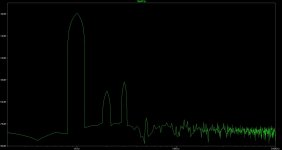
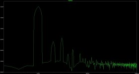
And here are the distortion spectra where VAS indicates distortion prior to the output triple in the Mk2 and at the bases of the "stasis" transistors in the transimpedance version.
Attachments
Hi Analog_SA,
Really outstanding and painstakingly job you performed.
Questions is if Jeff Rowland really swapped at it's Series III incarnation of the M7 to the encapsulated frontends to hide the implementation of those IC's that are not usually associated with highend sound.
I think collegues like Nelson Pass and John Curl won't react to your findings out of courtesy for a fellow designer although I would be very interested in their professional opinions.
As you already know I can't comprehend your findings but having had the same amp twice (silver and satin black version) and also for three years a slate grey Series II, I found the transimpedance version the best sounding one on my Acoustats. I would recommend this amp to anyone who has a need for power combined with musicality. Together with the Levinson ML-2 and the Threshold SA/1 I found this Model 7 the best amp I had.
Nevertheless your perspective is a valid one and your entitled to criticise/have an opinion about the designchoises of a particular product although what you effectively say is that the frontend isn't that great (bit of an understatement in light of your remarks) and the outputstage is a copy of Thresholds Stasis section, hmm.
I'm curious what others like Jacco or Zen_mod have to say about the frontend of this M7 because really I can't say anything intelligent about it due to lack of knowledge. It does look pretty complicated compared to the frontend of my SA/1 optical bias though.
Please don't be shy!
Last edited:
I really don't see any Curl influence there. Perhaps you should ask him.
Maybe John Curl contributed to one of the predecessors of the Rowland Model 7 like the WL-500 that was manufactured for Roger West (West Labs, Soundlab) or the first Series M7.
I posted a thread with that question but got no response as I expected because this is a DIY forum and not a place to discuss who did what with whom...
I can imagine that it's a delicate matter because circuitdesigning is the creative process that's (or should be) the key element of any highend audio firm. I can imagine that as a designer you can get inspired or influenced by designs from others but it becomes thin line when your design leans heavily on another mans work and can't be called truly yours therefore.
Having said this I have not a single indication that's this is the case with any of JR's designs.
I'm still interested as Analog_sa the starter of thread, what are the opinions about his reverse-engineering frontend of the M7 and the 'Stasis' outputsections as he describes it.
As said before I fully understand that NP or for that matter JC, won't comment on a fellow audio-designer's circuit.
jeff rowland model 3 driver module broken
I wonder if some one has information regarding the driver module for an old Rowland design group model 3 amplifier.
I tried to look in it, but unfortunately when used the chemicals for dissolve the resin (for sure I picked the wrong one) I destroyed the components, the pcb barely survived but is not much helpful.
As far as I know this is a common failure on these amps, due the stability of design.
Does anyone has the schematic for this amp or an improved circuit to drive the output? transistors are 2AS1073 and 2SC2523, I don't know if they are on stasis configuration or class AB.
any help is welcome.
Hi Analog_Sa.After a mishap with one of the potted modules of my Model 7 i got curious and took a peek inside. Always wondered why it sounded dull and attributed this to filter caps, passive components and execution. After all, based on this very useful post of BrianEno http://www.diyaudio.com/forums/pass-labs/186060-threshold-sa-4e-vs-sa-1-a.html#post2547185 and the quote from the Model 7 user's manual "Lack of overall or nested negative feedback eliminates time domain distortion" made me think that conceptually at least, this amplifier was indeed excellent.
Output stage is identical to the Threshold Stasis amps where it is similarly not within a NFB loop. John Curl once mentioned being a consultant for the early JRDG amps and this meshed well with the Mk2 input schematic shown in BrianEno's post above. Can you possibly combine Curl and Pass and not achieve greatness?
A bit of historical background may be useful here. The Model 7 was initially produced in non-clandestine fashion. Eventually a Mk3 with an epoxied front end was introduced, followed by a "transimpedance" upgrade module which allowed Mk3 owners to obtain an even better performance. My set of Mk3 amps came with the "transimpedance" module installed.
So, after a bit of digging through some of the hardest epoxy known to man i came up with a circuit diagram. It may not be 100% correct as the reverse engineering exercise was a bit messy but the results are, nevertheless, interesting.
To begin with, there are two medium quality double opamps per channel which serve as balanced to single ended convertor, allow adjustable voltage gain, output dc servo and provide the important low impedance drive for the transimpedance section. I find this quite amusing. A high end manufacturer seems to have more scorn for audiophiles and their hearing than even hard core objectivists. So, the signal has passed through hundreds of opamps, what can another three do?
Adding further insult is the power supply arrangement for the opamps: 400uf per rail followed by a pair of 12v zeners, followed by about a foot of wire. No local decoupling of any sort that i could find. Imagine the poor audiophiles trying to find a matching zero NFb preamp for their Rowlands. The travesty of the high end.
To clearup the matter I used the name 'BrianEno' at first and for obvious reasons I changed it to RobertS61.
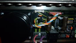
The 400uF per rail you talk about is situated on the powersupply assembly constituting of eight times 100uF/200V electrolytics (C15-C22, RMRM 105 Celcius). As far as I can see the epoxy audio-board is fed by it's own regulated powersupply with its own potted toroidal transformer, bridge rectifier CSB6 with snubbers and the 400uF smoothing caps per channel to get a +/- 120 Volts regulated line for the mainboard.
Then trough a Jumper J8 it's indeed fed through wires to J2 jumper on the mainboard that holds the epoxy filled audioboard.
In contrary I believe I'm not a technician, there are some filmcaps on the mainboard. The +/- 90 Volts has its own 10uF/100V and 22uF/150 filmcaps (white) and the +/- 120 Volts has a .56uF/200V filmcaps (yellow ones) added. Wouldn't you consider that as a form of decoupling? The pre-driversection with the opamps is fed by the regulated +/- 120 Volt and the driversection with the +/- 90 Volts.
Do you still have these amps (I doAnd then there is the actual power amp. Unlike Rowland's claims it is quite the opposite of feedback free. It has, however, a rather interesting circuit. I certainly do not understand it completely and fail to translate it to standard topologies. The output, biasing, servo and input stages are clear but i really get lost with the workings of the current mirrors. If anyone feels up to analysing this ciruit it will really be appreciated. The front end seems a bit similar to the Chinese Model 9 clone circuit which i am not even sure is entirely correct http://www.diyaudio.com/forums/solid-state/50083-jeff-rowland-model-9-amp-schematic-really.html
I simmed both Mk2 and Mk3. Unsurprisingly, most of the distortion is generated in the output stage. It seems excessive, so maybe something is not quite right with my sims. The "stasis" pair is certainly the most critical part of the design. I couldn't find models for the 2SA1073/2SC2523 originally used and replaced them with 2SC2922/2SA1216 which should be at least as good. The servo is omitted for simplicity but would normally connect to the grounded side of R36 on Mk3 and R41 on Mk2.
As much as i like the Mk2 curcuit, transistor matching and precise setting of the input current sources is probably not easy. Could it be the reason JRDG quietly abandoned this circuit?
R35/R37 in the transimpedance sim were actually inductors. Forgot to measure them.
Eventually, i will probably build several front ends while retaining the Threshold output stage. Maybe a Threshold, a Mk2 and a Mk3 but with proper opamps, properly powered. Looking at the really high distortion at output i am not so convinced it is a great idea, but converting to a standard emitter follower output stage under a feedback loop may just be too hard for me.
I hope these circuits are of some interest to others as well. Any suggestions, corrections and modifications are most welcome.
) and did you built your own front-end without the opamps (like the Series II which was the first model 7 I had back in the nineties). Are you sure that the outputstage is in fact a Stasis design as you stated? Nelson Pass had the Stasisprinciple succesfully patented in the early eighties and the first model 7 appeared in 1984....http://www.diyaudio.com/forums/attachment.php?attachmentid=602368&stc=1&d=1488458588
http://www.diyaudio.com/forums/attachment.php?attachmentid=602369&stc=1&d=1488458588
http://www.diyaudio.com/forums/attachment.php?attachmentid=602370&stc=1&d=1488458588
Attachments
Questions to the Jeff Rowland's (JRDG) Front End Unit in potted Version from Model 7
questions to the Jeff Rowland's (JRDG) Model 7 Front End Unit in potted Version
I've often have heard in recent years, that this resin encapsulated module of model "7" is often broken.
Now I have two of this monaural power amplifier on the desk with such front ends.
To get ahead, there is no way around opening one of the module to create the associated schematic diagram (Mr. Jeff Rowland don't release the schematic).
But before I start, I would have additional faulty modules, at least 4 additional pieces (a request on Ebay should lead to some offers).
Therefore I would have to know, if the different "Model 7" versions also have different modules or not.
According the images under
The jeff rowland power amplifier Museum - Hifi audio
the "Model 2" (Stereo version) and "Model 7" uses the same version - check also post #6 under
Rowland Research Amplifier Help!
But of both models there are different versions.
Under
Old Jeff rowland Model 7 monos | What's Best Audio and Video Forum. The Best High End Audio Forum on the planet!
I read as follow (post #4):
The Jeff Rowland model 7 had three versions, and each sounded different. The first one was unbalanced and, although less detailed and fast then the next generations, had a typical coloration that could sound very nice. Later versions were more neutral. I had some special consideration for the mk3, that paired with the matching Coherence One series 2 could make a great system.driving a pair of IRS Beta speakers. The Rowland 7s were full bodied and, with a powerful bass, but by modern standards were not very articulated in the lower frequencies. They also sounded excellent with electrostatics, such as Soundlabs. The model 5, a lower power stereo version of the 7s was one of best sounding solid state amplifiers to drive the Quad ESL63s. BTW, as far as I know no Rowland amplifier was class A.
check in this case also out post #7 under
Info Jeff Rowland & Rowland Research model 7
Are the associated resin encapsulated modules also different or not ? - that is now for me the most important question.
In terms of appearance, these encapsulated "lunchboxes" could be identical at least between the MK-I and MK-II versions - go therefore to the images from post #1 under
Jeff Rowland Model 7 serie II
and compare it with the images under
The jeff rowland power amplifier Museum - Hifi audio
Thank you very much for some advices.
P.S.: Obviously one of the member had already open that box:
Some questions about Jeff Rowland model 7?
After removing the resin, separate the copper tracks and the solder joints and then check the components (resistors, capacitors and transistors/diodes) by measuring without seeing and destroy them.
However, this does not work, if the encapsulated PCB is a multilayer version, unfortunately.
questions to the Jeff Rowland's (JRDG) Model 7 Front End Unit in potted Version
I've often have heard in recent years, that this resin encapsulated module of model "7" is often broken.
Now I have two of this monaural power amplifier on the desk with such front ends.
To get ahead, there is no way around opening one of the module to create the associated schematic diagram (Mr. Jeff Rowland don't release the schematic).
But before I start, I would have additional faulty modules, at least 4 additional pieces (a request on Ebay should lead to some offers).
Therefore I would have to know, if the different "Model 7" versions also have different modules or not.
According the images under
The jeff rowland power amplifier Museum - Hifi audio
the "Model 2" (Stereo version) and "Model 7" uses the same version - check also post #6 under
Rowland Research Amplifier Help!
But of both models there are different versions.
Under
Old Jeff rowland Model 7 monos | What's Best Audio and Video Forum. The Best High End Audio Forum on the planet!
I read as follow (post #4):
The Jeff Rowland model 7 had three versions, and each sounded different. The first one was unbalanced and, although less detailed and fast then the next generations, had a typical coloration that could sound very nice. Later versions were more neutral. I had some special consideration for the mk3, that paired with the matching Coherence One series 2 could make a great system.driving a pair of IRS Beta speakers. The Rowland 7s were full bodied and, with a powerful bass, but by modern standards were not very articulated in the lower frequencies. They also sounded excellent with electrostatics, such as Soundlabs. The model 5, a lower power stereo version of the 7s was one of best sounding solid state amplifiers to drive the Quad ESL63s. BTW, as far as I know no Rowland amplifier was class A.
check in this case also out post #7 under
Info Jeff Rowland & Rowland Research model 7
Are the associated resin encapsulated modules also different or not ? - that is now for me the most important question.
In terms of appearance, these encapsulated "lunchboxes" could be identical at least between the MK-I and MK-II versions - go therefore to the images from post #1 under
Jeff Rowland Model 7 serie II
and compare it with the images under
The jeff rowland power amplifier Museum - Hifi audio
Thank you very much for some advices.
P.S.: Obviously one of the member had already open that box:
Some questions about Jeff Rowland model 7?
The best way is to remove the resin by grinding only on the solder side of PCB until the tracks and solder joints are just visible.I wonder if some one has information regarding the driver module for an old Rowland design group model 3 amplifier.
I tried to look in it, but unfortunately when used the chemicals for dissolve the resin (for sure I picked the wrong one) I destroyed the components, the pcb barely survived but is not much helpful.
As far as I know this is a common failure on these amps, due the stability of design.
Does anyone has the schematic for this amp or an improved circuit to drive the output? transistors are 2AS1073 and 2SC2523, I don't know if they are on stasis configuration or class AB.
any help is welcome.
After removing the resin, separate the copper tracks and the solder joints and then check the components (resistors, capacitors and transistors/diodes) by measuring without seeing and destroy them.
However, this does not work, if the encapsulated PCB is a multilayer version, unfortunately.
some advices to Jeff Rowland's model "7"
JRDG Company Special – Model 7 | HFA - The Independent Source for Audio Equipment Reviews
JRDG Company Special – Model 7 | HFA - The Independent Source for Audio Equipment Reviews
- Status
- This old topic is closed. If you want to reopen this topic, contact a moderator using the "Report Post" button.
- Home
- Amplifiers
- Solid State
- Deconstructing Rowland 7