Hi all,
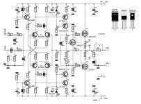
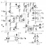
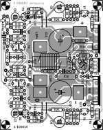
I just finished two boards of my Crescendo ME amplifier + switch on delay board
After the first startup, everything looked fine, red leds glowed, Re1 and Re2 on protection board switched,
and the voltage at tp3 was below 0.1V, (0.057V after 1 minute but still oscillating).
But after 2 minutes, the heatsink were very hot and R32 and R32 burnt !!! And I immediately turn off the power supply.
Here is my actual settings:
- I use 2SK2733 instead of 2SK537
- I use OP177GPZ instead of OP77GP
- I use a temporary heatsink just for test purpose. it's a L profil in aluminium (1 meter long)
- the potentiometer is full range => 1K
- all power transistors are electrically isolated from the heatsink
- there is nothing in input / nothing on output
- I use rectangular red led stick with strong glue with T5 and T6
- I use standard component with standard tolerance
- I notice that after the crash, fuse on my power supply still working
I have few questions as I'm a newbie in building amplifier
- Do I need to fix power transistor on the heatsink to make the setting of the board ie. nothing connect in and out? (I presume no but I don't know)
- Is it normal to have the heatsink very hot (I presume no!) ?
- What is the best recovery plan at this point ?
- What is the best value for the fuse on the switch-on delay board(currently 10A, probably too high I suppose)
- What could be wrong (no idea on this point") )
)
Thanks for your help
I just finished two boards of my Crescendo ME amplifier + switch on delay board
After the first startup, everything looked fine, red leds glowed, Re1 and Re2 on protection board switched,
and the voltage at tp3 was below 0.1V, (0.057V after 1 minute but still oscillating).
But after 2 minutes, the heatsink were very hot and R32 and R32 burnt !!! And I immediately turn off the power supply.
Here is my actual settings:
- I use 2SK2733 instead of 2SK537
- I use OP177GPZ instead of OP77GP
- I use a temporary heatsink just for test purpose. it's a L profil in aluminium (1 meter long)
- the potentiometer is full range => 1K
- all power transistors are electrically isolated from the heatsink
- there is nothing in input / nothing on output
- I use rectangular red led stick with strong glue with T5 and T6
- I use standard component with standard tolerance
- I notice that after the crash, fuse on my power supply still working
I have few questions as I'm a newbie in building amplifier
- Do I need to fix power transistor on the heatsink to make the setting of the board ie. nothing connect in and out? (I presume no but I don't know)
- Is it normal to have the heatsink very hot (I presume no!) ?
- What is the best recovery plan at this point ?
- What is the best value for the fuse on the switch-on delay board(currently 10A, probably too high I suppose)
- What could be wrong (no idea on this point
) Thanks for your help
Attachments
A)
are you using the genuine Elektor printed circuit board ?
make sure your power supply wires have the lenght they will have when everything will be inside the cabinet
make sure your temporary heatsink is grounded
make sure the speaker ground terminal goes to the power ground (R36 and C11 need to operate nominally)
make sure you don't input audio in the amp - don't let the input floating - use a 2.2K ohm resistor for emulating the audio source (volume pot resistance).
make sure R34 and R35 are not wirewound resistors (they are inductive)
B)
if still kaput,
make sure C13 and C15 are ultralow ESR
in order to get C13 and C15 ultralow ESR, decrease their values to 220µF or so (high quality Panasonic)
add an ultralow ESR capacitor 47µF between V+ and V- (high quality Panasonic)
C)
if still kaput,
remove R30 and R31 (they cause ground pollution)
replace MJE340 MJE341 by BF469 BF470 - read post #16 in http://www.diyaudio.com/forums/solid-state/194780-borbely-lender-true-symmetry-2.html
D)
if still kaput :
modify R10 C4 / R15 C5 values : try double the resistor and half the resistor, and try double the capacitor and half the capacitor
E)
if still kaput :
add a RC series network in parallel with R23 : try 1.2K ohm + 2.2 pF
and try new R10 C4 / R15 C5 combinations in D)
As you may have noticed, there are no Miller capacitors so this amp is quite critical regarding the stabiity. The stability occurs thanks to the R10 C4 / R15 C5 values. If you have trouble, adding add a RC series network in parallel with R23 may help.
If you can't stabilize the amp, then very sorry you will need to add Miller capacitors.
T8 collector to T7 base, 10pF
T10 collector to T9 base, 10pF
And possibly remove R10 C4 / R15 C5
regards,
Steph
Last edited:
Hi,
first of all, did you try without the protection card ?
Please do not remove R30/31 ! Make any modification. It is a good amplifier. Try to find the problem before make some modifications.
For test, you can insert a resistor of 10 ohms/5w in each polarity between amplifier and power supply.
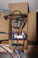
Your picture do not show power supply. Could you post a picture showing the complet amplfier ?
Regards
Frédéric
first of all, did you try without the protection card ?
Please do not remove R30/31 ! Make any modification. It is a good amplifier. Try to find the problem before make some modifications.
For test, you can insert a resistor of 10 ohms/5w in each polarity between amplifier and power supply.
Your picture do not show power supply. Could you post a picture showing the complet amplfier ?
Regards
Frédéric
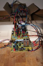
Some pictures...
choix d'un crescendo - ELEKTOR.fr | Électronique : Analogique Numérique Embarqué Microcontrôleurs Audio Test Mesure
Regards
Frédéric
choix d'un crescendo - ELEKTOR.fr | Électronique : Analogique Numérique Embarqué Microcontrôleurs Audio Test Mesure
Regards
Frédéric
thanks steph_tsf and frederic75 for your anwsers.
Steph, here are my answers for your questions
- Are you using the genuine Elektor printed circuit board ?
=> Yes
- make sure your power supply wires have the lenght they will have when everything will be inside the cabinet
=> It should be good
- make sure your temporary heatsink is grounded
=> My heatsink is not grounded, I would ground it now
- make sure the speaker ground terminal goes to the power ground (R36 and C11 need to operate nominally)
=> It's not grounded right now, I would ground it now- make sure you don't input audio in the amp - don't let the input floating - use a 2.2K ohm resistor for emulating the audio source (volume pot resistance).
make sure R34 and R35 are not wirewound resistors (they are inductive)
=> There is no audio in the amp, I would try with a 2.2k resistor as input.
=> R34 and R35 are MPC71 type, it sould be ok.
Frederic
=> I didn't try without the protection card, but i would disconnect it in my next test
I add a picture of my power supply
First I try with your advises and I let you know.
Thanks a lot
Attachments
Before powering the amplifier :
- read post #18 and #21 from http://www.diyaudio.com/forums/elektor/27423-update-elektor-crescendo-power-amplifier-1982-a-2.html
- check with an ohmmeter if the MOSFETs are still okay : high resistance between gate and drain, and between gate and source
- put the trimmer defining the bias current in the mid position
- double check if there isn't any ground loop formed by the ground supply wire and the speaker ground wire
Steph
Last edited:

There is a flaw in the Crescendo Millenium PCB design : all the grounds do merge. Not sure if this explains your stability problem.
I would however recommend :
- cutting the copper between the "LSP-" and "0" terminals
- using "LSP-" as "signal ground" (input ground and feedback ground)
- "signal ground" wired to your stereo cinch-in ground
- stereo cinch-in ground wired to the power supply star ground
- using "0" as "power ground" wired to the power supply star ground
- no need to change anything regarding R36 and C11 : they remain connected to the "power ground" on the PCB
- connect the return wire of the speaker to the power supply star ground
p.s.
The reason why Elektor merged all the grounds on the PCB is to avoid a risk like you assembling the amplifier, and powering it without connecting the signal ground to the cinch ground and the star ground. If you do so you, the amp may deliver a 50Hz square wave, rail to rail, and your (possibly expensive) speakers will be damaged. You are now warned !
Steph
Attachments
Last edited:
hi ,
not yet because one of my FET looks dead ! and I need to repair it
but I have the other card. I didn't test it yet because I'm afraid that the same problem occur.
I want to test it with your advise => 20 ohms /5W resistor + fuse on each polarity without protection card
what do you think ?
not yet because one of my FET looks dead ! and I need to repair it
but I have the other card. I didn't test it yet because I'm afraid that the same problem occur.
I want to test it with your advise => 20 ohms /5W resistor + fuse on each polarity without protection card
what do you think ?
- Status
- This old topic is closed. If you want to reopen this topic, contact a moderator using the "Report Post" button.
- Home
- Amplifiers
- Solid State
- Another Crescendo ME Problem...