Klippel is working on a model for 40years. I think his latest model has 100 plus components.
This is just a basic overview :http://www.klippel.de/fileadmin/kli...rature/Papers/Klippel_Nonlinearity_Poster.pdf
Why not connect a speaker while measuring ? OK; it gets pretty nasty loud.
This is just a basic overview :http://www.klippel.de/fileadmin/kli...rature/Papers/Klippel_Nonlinearity_Poster.pdf
Why not connect a speaker while measuring ? OK; it gets pretty nasty loud.
I do not understand why they do not provide an easy square waves generator, where you set the frequency, the level, and the offset... and, by default potentiometers, trasfos, and some other very ordinary parts we use all the time.
Hi Christophe.
Simetrix is the answer. I use it to sim everything from solid state relay to resonant ZVS flyback converter to SSA.
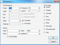
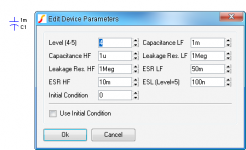
It has an easy square/sine/saw/triangle/pulse generator with offset/delay and other parameters. Also a bidirectional pulse generator, potentiometers, electrolytic caps, inductors and transformers. All with settable parameters and a very easy interface.
")
Attachments
Thanks a lot, Shaan, i will try this.Hi Christophe.
Simetrix is the answer.
BTW; interesting sims, may-be ?
My amp CFB vs VFB. The two sims are from the upper input VAS stage.
Don't compare the two low and high ends frequencies, the CFB is bandwidth limited for production, while VFB tuned to explore extremes.
Attachments
The graphs are difficult to compare because the scales are not synchronized.
Both CFB and VFB depend heavily on implementation. I'm not sure what part of the circuit these traces are from but I would guess the input stage for the VFB version has much higher transconductance necessitating more compensation to load it down enough at RF to stabilize it.
If the traces are taken from the VAS input, then the rail voltage variations will be added to the signal, obscuring the actual behavior of that node. Unless you used perfect voltage sources for the supply.
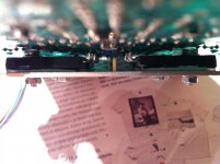
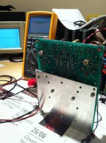
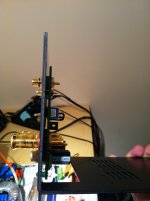
CSA prototype functional at last. Today I installed output BJTs, so the output BIGBTs are finally completed. Closed loop stability compensation scheme without any change as expected, output bias tested up to 0,5 A, DC offset +/-10 mV, very stable output. Sine waves from generator OK, 100 kHz square waves OK. The only thing left to finalize is temperature compensation for the main heatsink, 10 k NTC used as temperature sensor (pic), only 15 pF from NTC to housing (case GND) means also from VAS output to GND.
CSA's next stage is to finish the second channel and housing with heatsinks, toroids, etc.
CSA's next stage is to finish the second channel and housing with heatsinks, toroids, etc.
Attachments
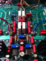
CSA prototype functional at last. Today I installed output BJTs, so the output BIGBTs are finally completed. Closed loop stability compensation scheme without any change as expected, output bias tested up to 0,5 A, DC offset +/-10 mV, very stable output. Sine waves from generator OK, 100 kHz square waves OK. The only thing left to finalize is temperature compensation for the main heatsink, 10 k NTC used as temperature sensor (pic), only 15 pF from NTC to housing (case GND) means also from VAS output to GND.
CSA's next stage is to finish the second channel and housing with heatsinks, toroids, etc.
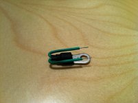
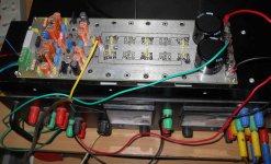
What and why are those wire soldered to the fuses?
hehe in testing phase instead of a real fuses, blown ones takes their place. Those wires connects 25 ohm/20 W resistor on both rails to prevent any outputs damage when closed loop stability is calibrating to optimal local feedback C. I use trimmer C on both VAS sides to find optimal capacitance. In CSA they're around 10 pF.What and why are those wire soldered to the fuses?
Look at the phases sens and what happens around 1Khz. This does not change whatever the current values.The graphs are difficult to compare because the scales are not synchronized.
I'm bored with their stupid interface...
Programmers may see it from different perspective. As long as it has the tool to construct more functionality, it is a good engine.
You can use variables (parameters in LTSpice) and make general statements (and components) made from variables so the only thing you do when you want to do different function (e.g. analysis) you just right click on a set of statements, make them a "comment" and right click on another set and make them "SPICE Directive". All of these statements (and components) can be put on the top of the circuit such that when you create a new circuit, you just copy them using F6 and drag.
Just an idea/perspective.
I like that idea Jay.
Consider math programs. You have to know some sort of console interface/language. It is just too difficult to design a graphical interface that is more intuitive than a written equation. You cannot replace an equation with a bunch of buttons and sliders, and retain the flexibility of written math.
Some extra features would make LTSpice less tedious for sure. However if you really get deep into optimized design, you are going to end up designing your own functions anyways. Someone who uses all the advanced features of SPICE probably will not have such a need for a heavily scripted interface. People who expect to only use the graphical parts of LTSpice and still want the full functionality of simulation will find the program lacking. The program was most likely intended for people who already know their way around SPICE.
......CSA prototype functional at last.......
So how does it sound ? Compared with, for example, the schematic Nico used or any other commercial amp we know of.
This has become a really long and interesting thread !
Hi ashok
As you can notice from the pics this is testing assembly with thin alu plate to thermally connect all driver output transistors and NTC sensor. The plate has GND potential and serves to electrically/thermally simulate the heatsink and still to enable enough space to make all necessary testing evaluations easier, like to set compensation caps, minor parts value modifications etc.
Thermal capacity of the plate is zero, so all the power measurements and sound checks can be done later in the process when regular heatsink will be here. It is ordered, just waiting to be delivered and than I'll report about SSA CSA comparisons etc.
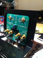
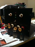
Before big heatsinks for CSA arrives I am actually not just waiting, for instance today I assembled real plate PCB to the case plate and installed all connectors, LEDs and remote/local trigger switch. Pictures says it all. 
Attachments
Hi all,
After a month's work, finally got my version of SSA singing...
It work's on +/- 65V with 3 pairs of Fet's. The Amp remains silent at switch on, no thump / noise. couldn't hear any hum / noise with my ears right on to the speakers, and now who said PSRR is not good with SSA....
And the sound....huge difference from my previous setup. Anyone who could hear the difference between a 5534 and opa134 opamp should be able to appreciate it.
Couple of observations....
I've adjusted the trimpot for near zero DC offset, after an hour with music at high volume the dc drifted from 3mv to about 45mv. Then i switched it off and on after a few minutes, and measured about 20mv. Is this normal...?
Also the resistor (3k3) that feeds from the base of driver cascode to base of input cascode does get uncomfortably hot to touch. My simulation shows little more than 1w of dissipation at @ +/- 75v. will Reducing the dissipation by increasing its value affect sound quality?
Everything else seems to work perfect...
After a month's work, finally got my version of SSA singing...
It work's on +/- 65V with 3 pairs of Fet's. The Amp remains silent at switch on, no thump / noise. couldn't hear any hum / noise with my ears right on to the speakers
, and now who said PSRR is not good with SSA.... And the sound....huge difference from my previous setup. Anyone who could hear the difference between a 5534 and opa134 opamp should be able to appreciate it.
Couple of observations....
I've adjusted the trimpot for near zero DC offset, after an hour with music at high volume the dc drifted from 3mv to about 45mv. Then i switched it off and on after a few minutes, and measured about 20mv. Is this normal...?
Also the resistor (3k3) that feeds from the base of driver cascode to base of input cascode does get uncomfortably hot to touch. My simulation shows little more than 1w of dissipation at @ +/- 75v. will Reducing the dissipation by increasing its value affect sound quality?
Everything else seems to work perfect...
Attachments

Also the resistor (3k3) that feeds from the base of driver cascode to base of input cascode does get uncomfortably hot to touch. My simulation shows little more than 1w of dissipation at @ +/- 75v. will Reducing the dissipation by increasing its value affect sound quality?
I think the input bias was specified for 10mA? With 10mA a 3K3 will dissipate 330mW.
- Status
- This old topic is closed. If you want to reopen this topic, contact a moderator using the "Report Post" button.
- Home
- Amplifiers
- Solid State
- Simple Symetrical Amplifier