Report on Shaan like basic LATFET SSA
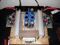
Went to a friend's to see and listen to his SSA build I was talking about lately.
Its based on Shaan's with the following differences:
1. No input coupling capacitor.
2. No 10K trimmers, no 1 Meg to input.
3. IR LED + 100R series trimmer output stage bias scheme instead of 2 X 1N4148. Bypassed by 470uF BGN as a whole. Gives freedom to match channels bias. Running at about 175mA in this amp's case.
4. 1.42K (1K2+220R) current feed resistor, its symmetric one is 1K trimmer + 500R in series. Does the offset trimming.
5. 270R instead of 220R as cascode load resistors. 1.5K instead of 2K2 feedback resistors. 24dB gain, 44dB OLG, 20dB FB instead of 27dB, 40.5dB, 13.5dB.
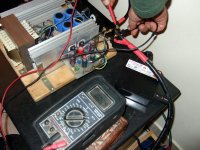
It did not show more than 10-15mVDC offset after many hours of play. No turn on thud, no turn off thud. Just a mute woofer pump maybe 1 or two 2mm pk-pk travel for less than 1sec at power off.
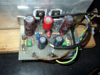
No noise no hum, built on iterated matrix boards, AC ground lifted though.
Smooth detailed expressive sound. Very good timing and presence. Maybe a bit softer than life IMHO in the brilliance region but it kinda shouted ''Latfet" to me about that trait. Fully retrieving though, just a slight tonal characteristic rather helpful with the many bit strident recordings or happier tweeters etc.
All in all, finally a current feedback rather simple 40-50W Mosfet amp you can expect it to succeed as a build when with typical DIY instruments and knowledge. Not too hot, not too big, but with a generous musical heart. Kudos to Shaan for arriving to a workable basic SSA with common semis example and sharing it, congrats to my friend Michael for keeping it stable when he reduced it to even less parts.
Went to a friend's to see and listen to his SSA build I was talking about lately.
Its based on Shaan's with the following differences:
1. No input coupling capacitor.
2. No 10K trimmers, no 1 Meg to input.
3. IR LED + 100R series trimmer output stage bias scheme instead of 2 X 1N4148. Bypassed by 470uF BGN as a whole. Gives freedom to match channels bias. Running at about 175mA in this amp's case.
4. 1.42K (1K2+220R) current feed resistor, its symmetric one is 1K trimmer + 500R in series. Does the offset trimming.
5. 270R instead of 220R as cascode load resistors. 1.5K instead of 2K2 feedback resistors. 24dB gain, 44dB OLG, 20dB FB instead of 27dB, 40.5dB, 13.5dB.
It did not show more than 10-15mVDC offset after many hours of play. No turn on thud, no turn off thud. Just a mute woofer pump maybe 1 or two 2mm pk-pk travel for less than 1sec at power off.
No noise no hum, built on iterated matrix boards, AC ground lifted though.
Smooth detailed expressive sound. Very good timing and presence. Maybe a bit softer than life IMHO in the brilliance region but it kinda shouted ''Latfet" to me about that trait. Fully retrieving though, just a slight tonal characteristic rather helpful with the many bit strident recordings or happier tweeters etc.
All in all, finally a current feedback rather simple 40-50W Mosfet amp you can expect it to succeed as a build when with typical DIY instruments and knowledge. Not too hot, not too big, but with a generous musical heart. Kudos to Shaan for arriving to a workable basic SSA with common semis example and sharing it, congrats to my friend Michael for keeping it stable when he reduced it to even less parts.
Attachments
BC550C,560C BD139,140 grade 10 Philips. Well, the Renesas 2SK1058 & 2SJ162 are 160V 100W devices with 150C silicon core melt point. I don't see RthetaJC (thermal resistance junction to case) in their datasheet. But from their derating curve it looks to be something like 1.25C/W RthJC. Don't give them more than 55V per rail and don't let them dissipate more than enough to go 120C internally max in any bias and sinks config. Typical Silpad adds 1C/W thermal resistance case to sink remember. You wouldn't expect good current @ 4 Ohm from anything single pair pushed beyond 60W amp anyway. Keep it there the most I would say, others may correct me.
The good one. Promise. Print and Iron.
I am apparently a rookie after all.
Thanks Naf.
dear shaan,
in your pee cee bee there is a diode 4744 which type of diode is this and which type of diode i i can replace?thanking you yours ever masood
Hi masood, this is 15V zener dioda rated 1W.dear shaan,
in your pee cee bee there is a diode 4744 which type of diode is this and which type of diode i i can replace?thanking you yours ever masood
It did not show more than 10-15mVDC offset after many hours of play.
It is not measured in significant conditions...
It s not enough to power on the amp , wait a few minutes
so the input stage transistors have reached thermal stability
but with almost no heat transfer from the power transistors
to the small signal parts.
What about if the amp is cased , what would be the thermal
influence on DC offset from powering on the amp until it has
reached the casing thermal stability after let say half an hour
at modest level..?..
It was playing for 5 hours on 87dB speakers, he lifted the TT arm and I took the offset photo. The sinks were warm to hot when touching and were radiating on the boards, caps being little warm. Had also stayed on overnight many times without DC run away he told me. That's all the info I got.
Hi masood, this is 15V zener dioda rated 1W.
dear naf,
thanks alot yours masood
Ok, thanksBC550C,560C BD139,140 grade 10 Philips. Well, the Renesas 2SK1058 & 2SJ162 are 160V 100W devices with 150C silicon core melt point. I don't see RthetaJC (thermal resistance junction to case) in their datasheet. But from their derating curve it looks to be something like 1.25C/W RthJC. Don't give them more than 55V per rail and don't let them dissipate more than enough to go 120C internally max in any bias and sinks config. Typical Silpad adds 1C/W thermal resistance case to sink remember. You wouldn't expect good current @ 4 Ohm from anything single pair pushed beyond 60W amp anyway. Keep it there the most I would say, others may correct me.
So if I put 8 ohm speaker & 60W that is safe...
")
& good heat sink of course.
But actually I want to push it up to 75W into 8ohm if possible with only 1 pairs output
I read earlier posts & find someone who broke 4 pairs of lateral
What usually cause the Latfet "go away" anyway?
Could anyone explain, this my first lateral & don't wanna fry them
Also no one use zobel network, not need for this amp?
thanks
Last edited:
Hi MiiB,
Thanks for the encouraging words...I've used the value of 1k from LC's schematic and haven't found any problem in simulation so far....As you've pointed out, i'l try to fine tune its value...
Hi LC,
Thanks you very much for the very interesting topology that you've given us...which actually got me in back to making amps... Yes...i'm planning to drive a pair of custom made 12" drivers...with this version of SSA beast.
Shaan,
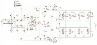
Here is the screen shot of the scheme based on post 347....
Thanks for the encouraging words...I've used the value of 1k from LC's schematic and haven't found any problem in simulation so far....As you've pointed out, i'l try to fine tune its value...
Hi LC,
Thanks you very much for the very interesting topology that you've given us...which actually got me in back to making amps... Yes...i'm planning to drive a pair of custom made 12" drivers...with this version of SSA beast.
Shaan,
Here is the screen shot of the scheme based on post 347....
Attachments
Ok, thanks
So if I put 8 ohm speaker & 60W that is safe...
& good heat sink of course.
But actually I want to push it up to 75W into 8ohm if possible with only 1 pairs output
I read earlier posts & find someone who broke 4 pairs of lateral
What usually cause the Latfet "go away" anyway?
Could anyone explain, this my first lateral & don't wanna fry them
Also no one use zobel network, not need for this amp?
thanks
You should look in the many threads here and for Exicon application notes to know all about Laterals. There is no secondary breakdown so the enemies are bad thermal design and/or oscillations mainly. I have another John Linsley Hood amp that runs one pair 2SJ50 and 2SK135 at 60V and 110mA on ~0.5C/W per channel sinks for 80W for instance but I don't think it has the same capability for running full out at 4 Ohm like it does at 8 Ohm. It has a series choke//resistor Zobel. You should have the swing from driving stage to do that though and you lose about 5V for gate drive VS BJT so its about 55V utilized for real even in that example again.
i'd like to use Laterals for drivers, to provide suffiecient current to charge / discharge input capacitance of these Vfets. I've sucessfully used this setup in another amp which i've made about 2 years ago. I've learned somewhere else from this thread that the PSRR is not great with this kind of topology and hence i've added a Cap multiplier at the rails to power input stage.
The amp performs brilliantly in simulation. The THD20 is less than 0.015% near clipping at 4 ohms. The square wave response is good, clipping action is excellent without any clamping diodes, etc. Now the question is will this circuit work...?as shown. comments please....
I didn't check your ASC file. But yes, the base front end with cascoded VAS as designed by LC has very low distortion. But when we believe that 0.001% is hardly different than 0.0001%, I cannot see no reason why to use cascode as I have suspicious with its sound quality unless another stage is added like in yours. Your output stage is very common and has good sound reputation and has been used in similar circuit of high end amp. I think the combination will produce very good or top result.
I will be building a cascoded VAS SSA without additional driver to see how good it can be. Rail voltage is 75V, bias is around 150mA. The good thing is that all harmonics are well below -100dB and the mosfet got more than enough current for a very wide bandwidth and speed. The bad thing is that it is not stable in simulation. After all other things have been "optimized" I can only get it to be stable against 27nF in parallel with load. But it seems that in real life it will have better stability.
Surprisingly, the SSA topology works very well with darlington outputs.
Temperature, and tension.What usually cause the Latfet "go away" anyway?
You will find in datasheets the"safe area" of them. You can evaluate the junction temperature, adding the case to junction thermal resistance and the case to radiator's one.
If you keep sufficient margin, you will be safe.
As other Fets, they do not suffer second breakdown, so they are very safe. Of course, and even if they are internally protected, take care the gate does not suffer from electrostatic discharge when you manipulate them.
If they are well sized, you have to be aware from HF oscillation. Amps can oscillate at a very high HF level, where dissipation, because the transition time, can be destroying, even if you are in the safe area with low frequencies. So limit the power rails current with a low power resistance or a fuse during your first power on, until you ensure your amp is rock stable.
Did i forget something ?
[edit] Yet answered by Salas, in the time i was composing this message, Sorry.
Last edited:
Kudos to you Sir to inform in this thread.Went to a friend's to see and listen to his SSA build I was talking about lately.
Its based on Shaan's with the following differences:
1. No input coupling capacitor.
2. No 10K trimmers, no 1 Meg to input.
3. IR LED + 100R series trimmer output stage bias scheme instead of 2 X 1N4148. Bypassed by 470uF BGN as a whole. Gives freedom to match channels bias. Running at about 175mA in this amp's case.
4. 1.42K (1K2+220R) current feed resistor, its symmetric one is 1K trimmer + 500R in series. Does the offset trimming.
5. 270R instead of 220R as cascode load resistors. 1.5K instead of 2K2 feedback resistors. 24dB gain, 44dB OLG, 20dB FB instead of 27dB, 40.5dB, 13.5dB.
It did not show more than 10-15mVDC offset after many hours of play. No turn on thud, no turn off thud. Just a mute woofer pump maybe 1 or two 2mm pk-pk travel for less than 1sec at power off.
No noise no hum, built on iterated matrix boards, AC ground lifted though.
Smooth detailed expressive sound. Very good timing and presence. Maybe a bit softer than life IMHO in the brilliance region but it kinda shouted ''Latfet" to me about that trait. Fully retrieving though, just a slight tonal characteristic rather helpful with the many bit strident recordings or happier tweeters etc.
All in all, finally a current feedback rather simple 40-50W Mosfet amp you can expect it to succeed as a build when with typical DIY instruments and knowledge. Not too hot, not too big, but with a generous musical heart. Kudos to Shaan for arriving to a workable basic SSA with common semis example and sharing it, congrats to my friend Michael for keeping it stable when he reduced it to even less parts.
how much supply of this SSA version?
Salas, i'm not sure of that (softer than life). I believe that is an effect of the speed quality of closed loop amps, to reduce the HF distortions witch gives slower amps a brighter character than expected.Maybe a bit softer than life IMHO in the brilliance region but it kinda shouted ''Latfet" to me about that trait. Fully retrieving though, just a slight tonal characteristic rather helpful with the many bit strident recordings or happier tweeters etc.
I had noticed the same effect on my amp, after SSA modification of it. Because it uses exactly the same active components, i'm pretty sure the components sonic characters were not involved.
Last edited:
That's what I heard but take it with a pinch of salt in the context of a full system. I remember it again in the previous less DC behaving attempts of that config still. That was remedied with the CCSs then, this example did not take them in his first attempt though, it latched to one rail fully biasing one half, so he reverted to resistive current feed. But he is the persisting kind of fellow, I am sure he will attempt it again. In any case of revision I will report.
Salas, take my remark with a pinch of pepper, as it address half of the situations we need to compare.That's what I heard but take it with a pinch of salt
Misses the comparison with the same topology between different power devices (BJT, Lateral, HEX vertical). Only way to figure out what can be the part of the topology, and what can be the one of any device's sound.
I believe that, with enough open loop gain and current feedback, distortion is low enough to erase any typical distortions (color) due to components non linearity.
I believe L.C. can say more about that, because his D amps is supposed to have *no analog sound*, means no 'color' influence of the switching device technology.
Surrealistically enough I got a phone call 15mins ago that he attempted 2 BF245C 14mA free IDSS matched equipped with source leg trimmers and prepared for 10.5mA this morning. He dropped them in instead of the current feed resistors and it looked it did OK. More monitoring and some listening in the evening he said.
- Status
- This old topic is closed. If you want to reopen this topic, contact a moderator using the "Report Post" button.
- Home
- Amplifiers
- Solid State
- Simple Symetrical Amplifier