thanks LC, 4 pr will work for me , if your current version can be made to do so ...
Hi a.wayne
There are some PCB-s published in a SSA thread. Nico made PCB at begining, bigun made it in his thread (SMT parts), there were some PCB proposals from Alex here in this thread. Many derivates, depends to SSA schematics variant choosen. For a SSA BIGBT HP I made PCB, as you've probably noticed, but than there was CCS PCB installed as add on module (separate small PCB) for better performance (more like R&D design).
As I remember you're interested in something more like Zout low (many output pairs) and that kind of SSA didn't arise yet.
Look I suggest you to concentrate to one specific schematic that will suit you and we can make it work and design PCB.
As you know now my work is concentrated to CSA which is combination of SSA and TSSA, which have two output pairs only.
Regards Andrej")

Hi LC and all. While going through old posts I noticed that nico's version has two 1n4007 in parallel to the 330ohm gain resistors. What is their purpose. Thanks.
Before the experts chimming in, here is what I understand...
The issue with SSA is the thermal effect on input BJT internal diodes. We want a stable bias regardless of temperature so we use (the same silicon) external diodes to stabilize current with temperature change.
The diodes will be clamped between 2 input stage Vbe (which has silicon diode), so we use also 2 silicon diodes for similar forward voltage drop.
Input stage TO92 transistors' Vbe is around 0v6 but I think more often around 0v64(?), while external diodes have higher variations in forward voltage, so caution must be used in choosing proper diodes.
You want a small voltage drop for the stabilization to be effective, but you don't want too low total drop (not too low than 2*Vbe of the input transistors) that will increase distortion.
It is easy to get sufficient voltage across input emitters (higher than 2*Vbe) with your 2K2 feedback resistor. I use smaller one (1K) for faster amp.
You can measure the voltage between input emitters without the compensation diodes like in your circuit. Lets say it is 1v3. You want sufficient drop to compensate the effect of temperature, but you don't want to have too much drop that may happen if you take diodes arbitrarily (may be there is also manufacturing variation?).
If you want to use 2 silicon diodes, I suggest you find diode with high forward voltage, like 0v8 or may be more. If you use 2x regular 1N4007 diode, you can insert in between, a very low forward voltage schottky diode capable of high current (low capacitance) that you can find in computer boards (SMD).
The more current thru the diodes, the more stable the voltage. Parallel capacitor also to stabilize the voltage across the diodes.
It is easy to get sufficient voltage across input emitters (higher than 2*Vbe) with your 2K2 feedback resistor. I use smaller one (1K) for faster amp.
My Fetzilla sounded much much better with 2K2 / 100 than with 1k / 50
1k may be faster but with same value of compensation it is less stable - it's was no brainer subjectvely
I did not yet try 3k3 / 150
2k2/100 5pf = perfect this time.
Your circuit can be further optimized (still raw), but in my book it has already outperformed Nico's version

Your circuit can be further optimized (still raw), but in my book it has already outperformed Nico's version
I have noticed in the simulator that the high order harmonics decrease in amplitude by half if the feedback and gain resistors are doubled in value. Might try it in future.
Although the bandwidth also decreases.
No need to fight with dates, Current feedback was used, long before solid state, in many tubes power amps, and was very common at this time. I don't know why this Graal turned as esoteric with transistor's invasion.
Like in music, nothing is never really new in electronic ;-)
In the same order of idea, the brilliant Lazy Cat's implementation is not very different from the Nelson Pass schematic: http://www.firstwatt.com/pdf/prod_f5_man.pdf where you can see current feed back divided in two branches to auto compensate the input stage offsets.
Despite this, Lazy Cat's SSA is very original and accurate.
If i have a special admiration to Mark Alexander, it is just for this intelligent combination of passive feedback mixing (CFB) and current mirror amplification of the resultant signal witch auto compensate localy the open loop high frequencies limitations. His schematic was at evidence for demonstration and educational purposes with the use of a integrated circuit amp to make the things very clear and understandable.
Special Special dedication to Analog Devices, too, witch had devoted a huge part of their business on very fast and affordable current feedback preamps both for audio and video.
Ps: You can seek during hours, Current feed back commercial amps are very few (far less than 1% of the market ?) and this is a thing that i have never understood.
Are-you living in the same world than us ?more like 50 percent
For consumer and PA, it may well be less than 1%. For high end audio, diy audio and non-audio the percentage is higher.
That said, CFB is "the" way to go if we want audio amps which are inherently stable without compensation and allow higher gain at higher frequency. This is for better transient response, something which is often felt more and heard less, i.e. the ultrasonics. The only obstacle is offset, to which SSA front end, when input bjts are thermally coupled, is a clear winner. I believe this config will soon enter the mainstream audio industry, as the differences are not only sonically better, but profitable too. This is because I built my SSA with less (active and passive) parts than my Blameless, and now the blameless is history for me.
That said, CFB is "the" way to go if we want audio amps which are inherently stable without compensation and allow higher gain at higher frequency. This is for better transient response, something which is often felt more and heard less, i.e. the ultrasonics. The only obstacle is offset, to which SSA front end, when input bjts are thermally coupled, is a clear winner. I believe this config will soon enter the mainstream audio industry, as the differences are not only sonically better, but profitable too. This is because I built my SSA with less (active and passive) parts than my Blameless, and now the blameless is history for me.
waiting sir Alex_mm making PCB layout from shaan's SSA schematic....
..... PCB for Shaan's schematic was done this weekend
as naf asked Regards Alex.
Attachments
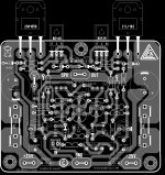
Last edited:
Nice one, Alex. Just a tip, if you bring CR ti the 2K2 by a separate little track right from the Speaker common point, you will really decrease distortion...... PCB for Shaan's schematic was done this weekend
Regards Alex.
Image just to make-it clear
Attachments
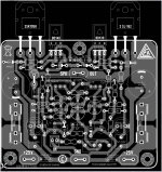
As always your capabilities are of the highest caliber! Nice Alex..... PCB for Shaan's schematic was done this weekend
Regards Alex.
Its my Nico Ras version..
Of course mosfets under the PCB
Of course mosfets under the PCB
An externally hosted image should be here but it was not working when we last tested it.
Attachments
- Status
- This old topic is closed. If you want to reopen this topic, contact a moderator using the "Report Post" button.
- Home
- Amplifiers
- Solid State
- Simple Symetrical Amplifier