Lazy Cat, I have one sitting behind me, it is a delay line, not a bunch of inductors or capacitors. I have another one inside my currently functioning Tektronix 465B. The delay line is used with triggered ramp (my memory is foggy here) to allow the variable delayed trigger feature on these scopes.
To measure the slewrate, you remove any filter before the input. Then you apply a square wave with a very fast transition time, at a very hight level, more than enough to bring the output of the amp to its max level. And you measure the transition time between 10% and 90% of the amplitude of the output signal.
Because the amp will not be able to follow the signal speed during the transitions, cr will not have time to send an inverted signal during those transitions, so the slew-rate is just a matter of the speed capacity of the amp in near open loop condition.
(Sorry for my poor english, i would be more comfortable to explain-it in French).
Not so sure, but thanksGold Star for explanation & English")
.Once we know the slew rate of our amp, we will have to filter the input signal with a low pass filter is such a way that never any incoming signal will reach this slew-rate slope in order to avoid TIM.
As LAZY CAT suggest in a humoristic way, we are not in concern with delay, in the CR of an amp. It is a group delay.
Just to consider each pole (stage) as a low pass filter. Open loop bandwidth will be the one of the slower one ( if Nyquist allows). and phase shift an addition of all individual poles phase shifts.
Well, in a conventional 'voltage feedback' topology, the signal is applied to the non inverting stage of the differential input stage, while CR is applied to the inverting input.
So there is an additional pole in the CR path (the inverting stage) before the two signal are mixed together. And this pole add his slew-rate and bandwidth limitation, phase shift, noise, distortion and saturation risk to the CR signal.
In a so called "curent feed back", the CR is mixed with the original strait at the output of the input stage. Without any additional pole*. That makes all the difference.
* if the CR resistance is low enough that capacitances to ground at the end of this resistance (acting as a low pass filter) have no or very little influence at our used frequencies.
Last edited:
(Sorry for my poor english, i would be more comfortable to explain-it in French).
I believe you know your stuff very well because I like how you explain the electronics things. But you like to use CR instead of FB. I believe CR stands for Contre Reaction (?), where word by word it doesn't make sense
* if the CR resistance is low enough that capacitances to ground at the end of this resistance (acting as a low pass filter) have no or very little influence at our used frequencies.
How about capacitor quality issue? I don't know why, I don't like the sound of a big cap in the feedback loop. If it is high ESR problem, I think theoretically it doesn't matter? 1000uF is not enough for 1K/35R but 2200uF. And once I forgot to replace back the cap with voltage source and I saw horrible simulation result?
I have tried to use opamp to eliminate the cap but it seems that opamps do not work in this circuit?
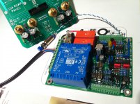
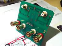
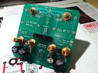
PCB-s for my new CSA amplifier, soft start & utility PCB, plus rear panel utility PCB already assembled. CSA channels PCB-s will go into production this week after extensive check-ups made, so all together four PCB-s and two toroidal transformers as a separate parts form new CSA amplifier. Rear panel connections in a previous, sold SSA, simply took too much time for all the wiring necessary. New PCB will make things much easier now ...
Attachments
Last edited:
Oh, so sorry. Thanks for the correction. Yes, In French "Contre Reaction" means exactly " Feed back". And years of habits...I believe you know your stuff very well because I like how you explain the electronics things. But you like to use CR instead of FB. I believe CR stands for Contre Reaction (?), where word by word it doesn't make sense
But, it is a pity, the forum do not let-me edit my post anymore.
Please forgive-me.
In a so called "curent feed back", the CR is mixed with the original strait at the output of the input stage. Without any additional pole*. That makes all the difference.
In the past, before SSA, there was only LTP input diff I used regulary (cascoded, mirrored, you name it ...), but was really never pleased with the sound, so after SSA they stayed where they belongs - in the past, at least as far as I'm concerned.
I believe CR stands for Contre Reaction (?), where word by word it doesn't make sense
Literaly translated , it s "counter reaction" , that is , not FB but NFB..
Hi, LC, beautiful, wonderful realization, as habit.New PCB will make things much easier now ...
I was talking about parasitic caps to ground.How about capacitor quality issue? I don't know why, I don't like the sound of a big cap in the feedback loop. If it is high ESR problem, I think theoretically it doesn't matter? 1000uF is not enough for 1K/35R but 2200uF. And once I forgot to replace back the cap with voltage source and I saw horrible simulation result?
I have tried to use opamp to eliminate the cap but it seems that opamps do not work in this circuit?
Well, If you are talking about high pass filter in the feedback loop to reduce DC shift, there is no reason why op amps did not work, as long you can find one with enough current capability (not so easy with low FB impedance) and, of course; low DC error. You can use too discrete transistors, or add a low impedance current amplification stage after the CI ?
I do not use active DC regulation, here, because i'm lazy, and never found any audible problem with good electrolytics, (not talking about their life duration), and because simple is beautiful. Why don't you try to parallel lighter ones (equal values) ?
If any issue with electrolytic caps, it will occur at high frequencies, and, as you said it is not so critical, here ? Proof ? The serial self of the electrolitic caps is acting like a cap in parallel with the FB resistance. Right ? And, on my amp, even with such a chemical cap i was obliged to add a little parallel cap with the FB resistance to smooth a little peak near the high extremity of the bandwidth.
I'm not sure if, for that kind of question, we can rely on simulations. too much parasitics elements, due to cabling, differences between components etc.. I had used stock electrolytic caps in real life. When i short circuit them, i don't hear such a difference in the sound on my system.
Last, if your amp is DC stable enough for DC shift don't reach a dangerous level: you can afford it without DC regulation, as L.C. did ?
Literaly translated , it s "counter reaction" , that is , not FB but NFB..
Oh, so that makes sense now
never found any audible problem with good electrolytics, (not talking about their life duration), and because simple is beautiful. Why don't you try to parallel lighter ones (equal values) ?
Actually I'm not sure if I have a big problem with the cap in the FB loop (even tho they are audible). It is just too big that I cannot use high quality cap and short path as I usually do. I use that axial ERO cap. Slightly to big for 2x1000uF and 1XMKP on top of each other.
Last, if your amp is DC stable enough for DC shift don't reach a dangerous level: you can afford it without DC regulation, as L.C. did ?
Ah, yes. I prefer this option than using opamp. Thanks to remind me, I will try this approach tho I have still to prepare the space for the cap on the PCB. I just wasn't sure if it was save due to possible issues external to the amp itself, like RCA cable plugged out while music is on, and the like.
Actually I'm not sure if I have a big problem with the cap in the FB loop (even tho they are audible). It is just too big that I cannot use high quality cap and short path as I usually do. I use that axial ERO cap. Slightly to big for 2x1000uF and 1XMKP on top of each other.
New CSA PCB has 28 transistors (bipolar, fet, mosfet), 7 TL zeners, separate power supplies for input and output, elcos in feedback GND connection, which can be disabled if prefered. All functional parts of each stage were tested separately and will be tested together at the first channel assembly in seeking to find optimum current-components values for complete front end. I will start with CCS-s, input stage, VAS and finally all together as voltage amplifier. Front end itself counts 22 transistors and 7 TL zeners which clearly indicates complexity but also opportunity to squeeze out maximum performance from all the stages. I am quite sure to know what am I looking for so the goal is well defined, the path to get there will be something like action road movie.
I am quite sure to know what am I looking for so the goal is well defined, the path to get there will be something like action road movie.
Is very good bass included in the goal definition? I hope so
In a so called "curent feed back", the CR is mixed with the original strait at the output of the input stage. Without any additional pole*. That makes all the difference.
The only difference wich yield an advantage is speed , for all the rest ,
particularly linearity , a VFB do better....
Front end itself counts 22 transistors and 7 TL zeners which clearly indicates complexity but also opportunity to squeeze out maximum performance from all the stages.
A chain resistance is the one of its weakest element , as such ,
it is useless to improve intermediary stages since the input stage
will inherently be the one that decide for the perfs , at least in
this kind of amp.
Remember that NFB provided by a following stage cant cancel
non linearity of a preceding stage...
Said shortly , the available gain of a VAS used for NFB
cant correct preceding stages in the global loop.
The only difference wich yield an advantage is speed , for all the rest ,
particularly linearity , a VFB do better....
Could not dissagree more. I really don't have time to explain the things that were already said in this thread before. The only thing VFB is better are DC conditions, but that we do not hear through our speakers. You should make one medium complex SSA and you'll get an impression of what we talk about here. LTP's are sounding dull compared to CFB.

A chain resistance is the one of its weakest element , as such , it is useless to improve intermediary stages since the input stage
will inherently be the one that decide for the perfs , at least in
this kind of amp.
Less talk more try. Besides at CSA's new input stage +20 dB gain is linear (-0,5 dB measured) to 3 MHz.
Last edited:
Is very good bass included in the goal definition? I hope so
When listened SSA with Ktema speakers, bass was for the first time integrated with the rest of the spectrum, superbly controlled. Other amps make this speakers looks like they have separate subwoofers with a little delay on lower notes.
Also at Piegas bass was perfect, as confirmed by very experienced recording-mastering engineer using the system for audiophile HR/CD production.
Last edited:
[snip]Remember that NFB provided by a following stage cant cancel
non linearity of a preceding stage...
Said shortly , the available gain of a VAS used for NFB
cant correct preceding stages in the global loop.
Apart from the fact that a stage doesn't 'provide NFB' this is incorrect.
If at any place within an nfb loop you increase gain you get a larger difference between open loop gain and closed loop gain.
And it is the difference between these two that determines how well the nfb improves the performance of the whole amp.
So in a power amp, with nfb from output to input, you increase the Vas gain, that definitely is of benefit to the amp performance.
jan didden
Jan , that s not correct , mind you...
When you increase the gain of the VAS , the added NFB can
reduce distorsion of the VAS as well as the one of the following stages ,
but it wont reduce distorsion from the preceding stage , let say the IPS ,
other than due to byproducts of this higher VAS gain , i.e , the IPS
will be less loaded since it will provide less output voltage to drive the VAS.
Edit : The IPS is not enclosed in the gain loop of the VAS ,
while the latter is enclosed in the IPS gain loop , all this
seen from a GNFB point of view.
Last edited:
- Status
- This old topic is closed. If you want to reopen this topic, contact a moderator using the "Report Post" button.
- Home
- Amplifiers
- Solid State
- Simple Symetrical Amplifier