thanks sheldon for the information, but as in the schematic, I didn't see where does the diode connection of thermal track (NJL have extra 2 legs than MJL)
If I just replace the NJL with MJL, what will degrade or fails ?
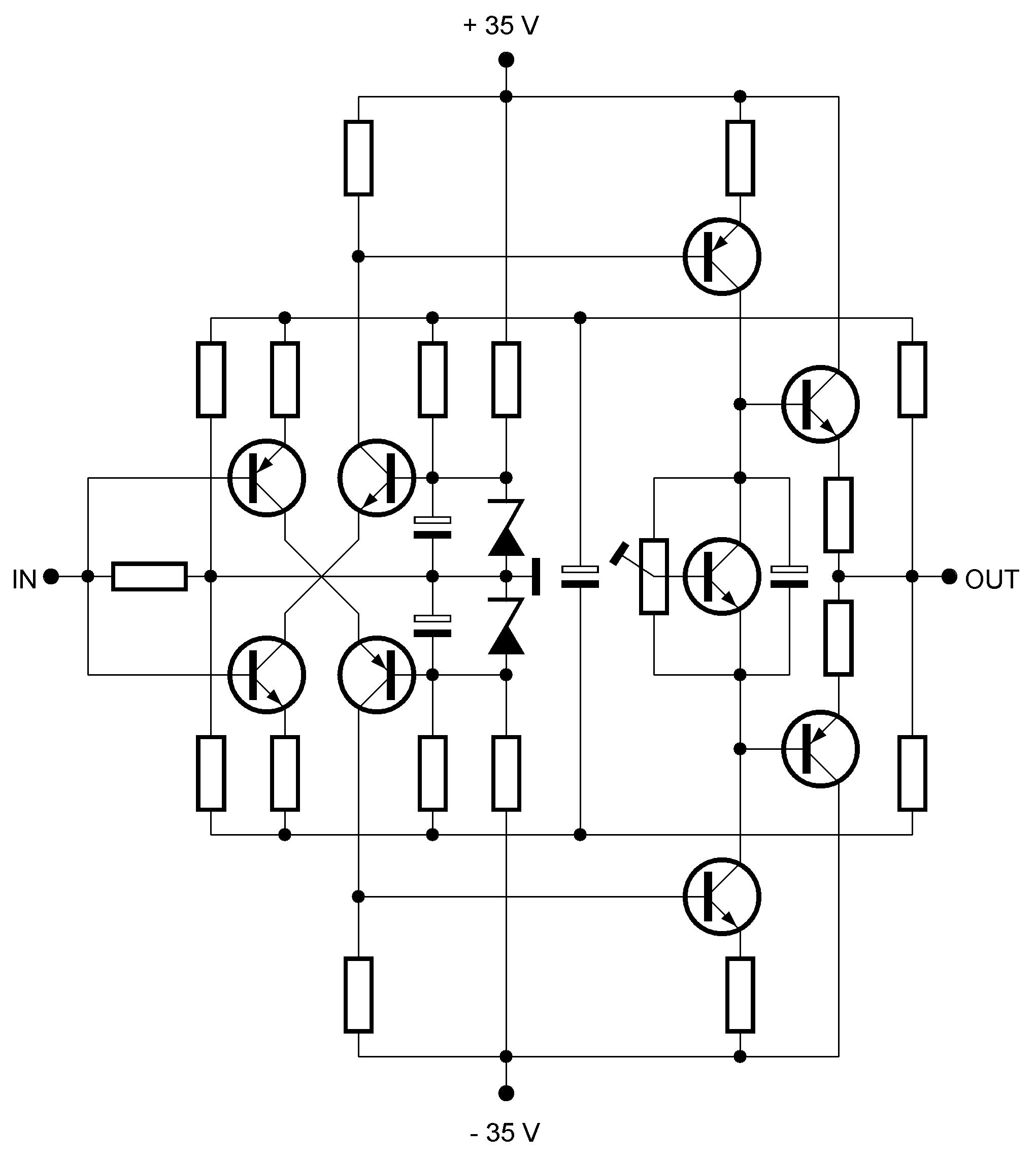
It's not obvious from looking at the schematic, but the biasing diodes are intended to be the diodes from the NJL part (the two extra legs are the diode). Since the NJL diodes are on the same die as the transistor, their temperature will closely track the transistor temperature.
As the transistor heats up, it's effective resistance drops and it will conduct more. Unless there is thermal compensation, this will generate more heat, leading to more conduction, etc., until it goes into thermal runaway.
The bias diodes in the schematic will heat at the same rate as the transistor. As they heat, their effective resistance also drops, which decreases the voltage spread between the bases of the output transistors. This decreased spread reduces the bias current in the outputs.
If the thermal properties of the diode and transistor are identical, then for this schematic, the changes with temperature will cancel each other. In fact, they are close but the design will be slightly under compensated.
Fortunately there is another thermal compensation mechanism at work: As the heatsink gets hotter, the temperature differential between it and the surroundings increases. Therefore it sheds energy faster. So if the amp is internally under compensated, a larger heatsink can make up the difference.
If you use MJL parts, then you might be able to use this schematic. But you will need to source a TO220 diode with the correct thermal properties and mount it on the heatsink - right next to the output transistor (or better yet, right on top of the output transistor). There will be more thermal lag between the transistor and diode than with the NJL part, but with some testing you should be able to get things safely balanced, with a good safety margin.
With either diode, you will want the amp to stabilize at less than 60 degrees, under the maximum power dissipation that you expect.
Sheldon
Last edited:
hm..... so to say, the NJL is way better than MJL+external diode combination. But in term of cost, will MJL combination is cheaper ?
Just to confirm, the NJL's diode in schematic is the beside 50R, left of individual NJL ?
If they were to absent, does it really cause thermal runaway ? (any other solution ?)
Just to confirm, the NJL's diode in schematic is the beside 50R, left of individual NJL ?
If they were to absent, does it really cause thermal runaway ? (any other solution ?)
hm..... so to say, the NJL is way better than MJL+external diode combination.
More elegant solution, yes. Way better in practice? I think the external diode can work almost as well.
Just to confirm, the NJL's diode in schematic is the beside 50R, left of individual NJL ?
Yes. They are the diodes in series with the 50R pot. BTW, the order doesn't matter as long as the three elements are in series. Looks nicer with this order on the schematic.
If they were to absent, does it really cause thermal runaway ? (any other solution ?)
Absent? You have to have something in that string to create a voltage spread of about 1.2V between the bases of the output devices. Simplest thing is a resistor, but that gives you no thermal compensation. With a big enough heat sink you can do this. Or, if you use lateral mosfets on the output, you don't need thermal compensation, because they conduct less as they get hotter.
Diodes are next simplest, and if on the die or heatsink will provide thermal compensation. A VBE multiplier, next. Here's the simple version of the multiplier: http://www.diyaudio.com/forums/atta...313313292-simple-symetrical-amplifier-ssa.jpg
Sheldon
Some progress on the Sziklai drivers 40W one. To remind, firstly a resistor between the driver collectors was highly unstable for output bias. Random OPT stage overbiasing incidents. Then one LED instead of a resistor stopped those. But the drivers could still run away on their own if the wind was blowing the wrong way. Unreliable. Seems that there is a solution now shows. A JFET CCS fixing the drivers. Remains to be seen if the offset will be innocuous in the long run, or what type fits best, some better values etc. Works for now.
Attachments
hm... if i were to buy an external diode, what requirement is there ? any suggestion or recommendation ?
(I will skip resistor solution) I heard that the biasing of this amplifier is a bit scary (easily over bias or something like that) should i make those 2 VR to what value first ? (maximum or minimum, for safety of my amplifier) typically weak and inexperience with biasing/DC offset adjustment.
There is a pair of zener diode in the center of schematic, is it 12V rating ? what is its function ? (I'm going to use 40V dual supply, should i change this value ? I will change the capacitor's voltage rating.)
a resistor between the driver collectors was highly unstable for output bias.
I always make the connection of the driver collectors through this resistor as shortest as possible (no more than 2cm). Will that affects stability?
It was just between the Mosfet legs. Nothing unstable frequency wise on signal, but could not hold bias. Now I put a CCS for it I have steady current. Started with LED instead, now I put back a resistor for ~1.7V between the gates to see if its better for offset behavior also.
Well i'm on the way to make my own opinion, as i have on my table two of those little amazing circuits. At least, i just believe in what i listen, when i believe in something, despite all the respect i deserve for you or my friend ;-)
I keep preciously my 2 Crescendo 140watts SSA modified powered under +- 70V to compare with those Class D 250W powered by +-70V (see what i mean ;-). And 2x 800W +- 70V SPMS to compare with my analog PSU.
You know, for me, like a jump in the 21th century.
To be honest, my actual system is so good that i'm terrified by this decision to mod-it from passive to digital active filtering
Well, my firt comparison between the same amp modified SSA or not (Voltage Feedback against Current Feedback) don't kill the flies. But i can assure a slight improvement in transparency and speed...
Not a huge difference, of course, but i appreciate.
This has been bothering me...
You seem to appreciate sound quality, but for so many years you could live with a Crescendo?? Then you mentioned that the SSA modification only gave a SLIGHT improvement to the Crescendo

I still have Crescendo module somewhere, and your modification is not that difficult to implement so may be I will try to build your SSA Crescendo anyway. Then may be I will implement the same mod to the Planteve's amp:
Attachments
If were to use diode, what diode are recommended ? (specs, type) Is this ok ? http://my.element14.com/on-semiconductor/mbr1545ctg/diode-schottky-15a-45v-to-220/dp/1431049.......Diodes are next simplest, and if on the die or heatsink will provide thermal compensation. A VBE multiplier, next. Here's the simple version of the multiplier: http://www.diyaudio.com/forums/atta...313313292-simple-symetrical-amplifier-ssa.jpg
What value should I use on capacitor parallel to the pot ? and what transistor should I use ? (I assume to thermally bond them, at least near and at the same heatsink ?)
The other component should be still the same value ?
Last edited:
If were to use diode, what diode are recommended ? (specs, type)
What value should I use on capacitor parallel to the pot ? and what transistor should I use ? (I assume to thermally bond them, at least near and at the same heatsink ?)
The other component should be still the same value ?
IN 4004/7 is fine.. You can easily mount it on the heat sink placing the two diodes under a suitable large washer and screwing them down on with a single screw. Use a little silicon grease to make a good thermal contact.
What I found 1n4004/7 are axial package, no TO-220 or similar package(flat surface), thus hard to mount on heatsink and difficult to transfer heatsink fully ?IN 4004/7 is fine.. You can easily mount it on the heat sink placing the two diodes under a suitable large washer and screwing them down on with a single screw. Use a little silicon grease to make a good thermal contact.
Member
Joined 2009
Paid Member
If were to use diode, what diode are recommended ? (specs, type) Is this ok ? ON SEMICONDUCTOR|MBR1545CTG|DIODE, SCHOTTKY, 15A, 45V, TO | element14 Malaysia
No, you want a standard type diode, not schottky. Regular or fast recovery is fine. May not find those in flat package, so Nico's or Bigun's mounting suggestions might be easiest. I think the diode in the thermaltrak is equivalent to MUR120, so something with specs. similar to that will work.
Sheldon
Well..... I don't like gluing things, and like to have full contact.(flat surface)No, you want a standard type diode, not schottky. Regular or fast recovery is fine. May not find those in flat package, so Nico's or Bigun's mounting suggestions might be easiest. I think the diode in the thermaltrak is equivalent to MUR120, so something with specs. similar to that will work.
Sheldon
Anyway, if there is no flat surface for me, I have this thing, is it usable in here ?
http://docs-asia.electrocomponents.com/webdocs/03a9/0900766b803a9cb4.pdf
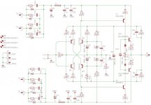
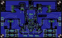
According LC schematic in this post :http://www.diyaudio.com/forums/solid-state/193923-simple-symetrical-amplifier-20.html#post2671820
Here my interpretation from ThermalTrak SSA (need to be verify)
NJL are mounted underbord as driver (2SC2911/2SA1209).
What about choice between NJL3281/1302 and NJL4281/4302?
Marc
Here my interpretation from ThermalTrak SSA (need to be verify)
NJL are mounted underbord as driver (2SC2911/2SA1209).
What about choice between NJL3281/1302 and NJL4281/4302?
Marc
Attachments
- Status
- This old topic is closed. If you want to reopen this topic, contact a moderator using the "Report Post" button.
- Home
- Amplifiers
- Solid State
- Simple Symetrical Amplifier