Yes, I've simulated it and the only amp of interest to me is the single lateral fet output version. All the different output configurations keeps this thread kind of a moving target. It's sure is interesting to see the variants but the simple version should be "fun". To me this is still very much an experimental circuit(s) since there hasn't been a whole lot of them built and I don't think anybody has run these many variations for hours and did some difficult/shorted load tests to see how it survives.
So you think I did not check?
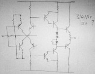
The input pair BJT's must have the same hFE and zero ΔT, in that case offset cancellation after I/V conversion is in direct proportion to ΔIcn-ΔIcp, which is automatically zero regardless T value.
The unique SSA's current feedback loop (bridge) has some specially good features still not really understandable to all ...
There s nothing specialy good since the global perfs seems average,
but it s true that the features are not well understood since the input
transistors Hfe has almost no importance as the bias circuit has low
impedance, hence the thermal stability is in proportion of the transistors
base/emitter voltages...
Member
Joined 2009
Paid Member
There s nothing specialy good since the global perfs seems average,
but it s true that the features are not well understood since the input
transistors Hfe has almost no importance as the bias circuit has low
impedance, hence the thermal stability is in proportion of the transistors
base/emitter voltages...
When DC offset is adjusted to zero V at the output, it actually means we compensated Vbe difference of the NPN/PNP input devices with the emitter currents correlation (Vben+Vren=Vbep+Vrep), after that ΔVoffset is only related to β/T dependence.
Global performance is even more average at LTP plus only one gain stage.
Last edited:
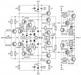
Actually, I realized that it's not post 183, 196 or 336 I'm looking for but a CFP driver and single EF output. Not sure if this will work but attached is what I have in mind. Yet another variation
It will work.
The second stage BJT is actually formed of a high current gain compound Darlington (Sziklai pair), which is in correlation of the max total gain we want to get in a simple SSA version like this.
Bigun I don't see anything stoppin' you at testing this version.
Last edited:
Yes, I've simulated it and the only amp of interest to me is the single lateral fet output version. All the different output configurations keeps this thread kind of a moving target. It's sure is interesting to see the variants but the simple version should be "fun". To me this is still very much an experimental circuit(s) since there hasn't been a whole lot of them built and I don't think anybody has run these many variations for hours and did some difficult/shorted load tests to see how it survives.
I tested BIGBT version extensively, high temp, many hours, signal generator, music, different loads, no compensation caps, no oscillations, clear clipping, ultra fast slew rate, no DC-offset variations ...
Please make a short circuit on any of your's amp without overcurrent protection ... I can imagine that too.

Last edited:
I like your approach, Bigun. Very elegant, and the emitter driver output will have low impedance and drive the output stage very well.
Let's see, base to rail resistor for predriver would be 1K, we could run the driver quiescent at around 30mA, and this means, assuming cascode current is 2mA, the predriver emitter to rail resistor would be 47R. With a Zout at each driver emitter of around 1R, you'd have enough drive to propel the USS Nimitz, and of course nice local feedback around the driver circuit. One change, however; I'd put a 1K resistor from emitter to base on each driver to ensure residual current at all times through the predriver.
Cheers,
Hugh
PS I'm not dead sure of the cascode current, but 2mA seems about right to me.
Hugh
Last edited:
I think the concept is very strong.. It scales easily.. can be fitted with a number of different output-stages....I am currently contemplating a version with a sort of current dumping configuration with laterals driving a number of BJT's
oh by the way the OLG...its about 70dB ant the OLB is app 50 KHz (-3 dB)
One thing i have trouble seeing through is how to adjust the current through the input pair/cascodes
oh by the way the OLG...its about 70dB ant the OLB is app 50 KHz (-3 dB)
One thing i have trouble seeing through is how to adjust the current through the input pair/cascodes
Last edited:
All the different output configurations keeps this thread kind of a moving target.
Please believe me that I have time and energy barely to handle this SSA thread, not even imagining to start another. New threads can be started as a specific type of SSA performed by successful builders, with their own explanations.
This thread is more educational one if you didn't notice by now but where can you learn more than at moving targets.
I like your approach, Bigun. Very elegant, and the emitter driver output will have low impedance and drive the output stage very well.
Let's see, base to rail resistor for predriver would be 1K, we could run the driver quiescent at around 30mA, and this means, assuming cascode current is 2mA, the predriver emitter to rail resistor would be 47R. With a Zout at each driver emitter of around 1R, you'd have enough drive to propel the USS Nimitz, and of course nice local feedback around the driver circuit. One change, however; I'd put a 1K resistor from emitter to base on each driver to ensure residual current at all times through the predriver.
Cheers,
Hugh
PS I'm not dead sure of the cascode current, but 2mA seems about right to me.
Hugh
Thanks Hugh for all your support.
Hopefully you will also find your favourite SSA someday to built.
Hi am most pleased with the L-MOSFET version and that is why I have not had any further contributions to the thread.
Those who want to run with the simplest of the suggestion would end up with an excellent product that will be very hard to beat.
I have compared to listening to the BJT version as well and cannot hear any difference that would make me prefer the more complex versions. The L-MOSFET version sounds absolutely superb, is unconditionally stable and currently used on 4 ohm speaker and 32VDC supply.
Kind regards
Nico
One thing i have trouble seeing through is how to adjust the current through the input pair/cascodes
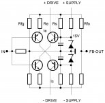
SSA front-end collector current:
Ic=Ie-Ic/β
Ie=((15V-0,6V-Re*Ie)/Rs)-((0,6V+Re*Ie)/(Rfo*Rfg/(Rfo+Rfg)))
Ic - desired cascode collector current
Ie - emitter current through input BJT
β - input BJT current gain
Re - input BJT emitter resistor
Rs - current supply resistor (resistor connected between 15V supply and emitter resistor)
Rfo - feedback resistor from OUT
Rfg - feedback resistor to GND
Simple as that.
Attachments
Last edited:
LC, you are being modest; no need for that, take a bow!!
I would say that your circuit is the fully complementary big brother to FetZilla, and one day I hope to compare the two.
I have a notion that the SE circuit will have higher even than odd order distortion.
Again, thank you,
Hugh
I would say that your circuit is the fully complementary big brother to FetZilla, and one day I hope to compare the two.
I have a notion that the SE circuit will have higher even than odd order distortion.
Again, thank you,
Hugh
- Status
- This old topic is closed. If you want to reopen this topic, contact a moderator using the "Report Post" button.
- Home
- Amplifiers
- Solid State
- Simple Symetrical Amplifier