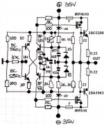
Can you make sim as proposed, turning the output mosfets to IGBT's?")
Yes I can. Which ones did you have in mind?
... or maybe just add this output buffer in microCAP to see if THD will lower substantially. If yes than we'll know that current feedback amp basic configuration cannot be easily to overcome.
Attachments
... or maybe just add this output buffer in microCAP to see if THD will lower substantially. If yes than we'll know that current feedback amp basic configuration cannot be easily to overcome.
Nice, but with HEXFET + BJT output stage the thermal compensation circuit (Vbe/Vgs multiplier) will have to replace the simple 1k trimmer...
What about a low power version for headphone use?
No problem it can be voltage/current scaled down and used with BC signal transistors only and IRF's at the output. But please wait untill we set the right topology with lower THD levels, than any version can be properly settled and calculated. Just wait what Nico will say ...
Last edited:
Lazy Cat that does not work. You substituted a Lateral MOSFET with a HEXFET. Biasing it is impossible. It switches between 22pA and 82 Amp. I will have to analyse it properly to find the solution. But personally I do not know why you want to mess with the schematic, rather make some real life measurement of what you have and give it a good listen. I will do the same during the week. I remain confident in what you have here is a very good amp.
Jaycee, a low power version is feasible, but you cannot just scale it. You would probably use BD139/140 for the output devices and run it off a +-6V supply, but there would be a number of value changes required. SIM predicts that it could work quite nicely as a headphone amp.
It is Lazy Cat's design so I leave it to him to decide.
Nico
Lazy Cat that does not work. You substituted a Lateral MOSFET with a HEXFET. Biasing it is impossible. It switches between 22pA and 82 Amp. I will have to analyse it properly to find the solution.
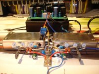
I know, you would need source resistor to stabilise IRF's drain current but it works perfectly cause I have tested and listened them. Now I know that my BIGBT's acted like an output buffer so distortion was infact low in my test amp. I have 100mA per each output BJT and it is very stable, also as you can see in previously posted pic that there is no heatsink at all and I could listen exact BIGBT combo for a few minutes before temperature went over 60°C.
The problem is that I write these lines from the sea and can not perform any tests right now, only communicate.
OK we'll try to stick to basic sch, fine tune the values and than make PCB.
As you probably know common topology to all current feedback amps is similar and combined from an input current diff amp, I/V conversion and output buffer, so the last is somehow missing in our primary sch.
Attachments

Yes.... better to keep this way..people can try and listen
the small distortion in the reality means nothing...it is not something bad.... there are lovely amplifier that distorts even more than that...the harmonic distribution is even more important.
Let's wait someone to assemble and report the audio quality..then you can decide if will try to change something or not.
I am following step by step and simulating each idea..i do like this amplifier but i am busy to build it...also i am not very addicted to Fets, iBGTs and others...i really love BJT...i feel myself at home with them.
Thank you... relax as you are in the sea..feel the fresh air in your lungs..... here is really hot these last days.
regards,
Carlos
Thank you... relax as you are in the sea..feel the fresh air in your lungs..... here is really hot these last days.
regards,
Carlos
Thanks Carlos, the sea today has very strong harmonic activity accompanied with fresh wind, very refreshing.

Deviation - general anomaly
Distortions are always present in analog amps, we could even say that there is only one general anomaly-distortion and that is Deviation - any possible difference from the original signal, except the gain factor. Deviation includes all measurable and unmeasurable details differentiate from the details of a signal present at the input. We would be quite sure that we are dealing with the perfect amplifier if deviation would be zero, but in the real world we have to be pleased with acceptable approximation only, the one which is acceptable to our measuring system - human brains. This one aproves everything better than the threshold level of our acceptance, so very forgiven factor. As long as any amp is over or better than this criteria I am pleased with it and this one belongs to that category.
So by this amp I am not worried about numbers not achieving five zeros, cause I experienced listening test and experience from other competent DIY-ers will also be relevant to evaluate the real value of this design.
I am also pretty sure that the main core of this schematics, feedback loop circuit around input pair, is very promising and can be expanded to more complex, precise designs at any time.
Last edited:
Interesting the therm used..... last time i heard about
deviation was while i used to adjust FM transmitters.
Yes...make sense to me all you said....but try to convince people that numbers means nothing...you will see them giving you a small smile and they will be thinking we are crazy...they believe in numbers.
They will think you are crazy cat in the place to be lazy cat...one thing is reality, other thing is what the majority of audiophiles thinks about.
There are some guys that has the faith connected to numbers....some of them say (and really think this way)... and they are not one or two..they are majority.
- If an amplifier measure good, then it is good....if numbers are small, then sound is good.... well...i strongly disagree..but they do not care about.
You do not need to convince me...i am already convinced about that since seventies...problem is to convince people...they will give us an yellow smile when we say that and will go away thinking we are retarded or something alike.
I can assemble to have fun, to my own use... but i would not waste my time offering high distortion numbers to the community because design will be snobbed...and happened tenths of times...i could see this happening.
If possible to reduce numbers..then do it...this way your lovely design will be much more accepted...one thing is reality..other thing is the reality people see inside their minds....that other reality is based in beliefs, prejudices, faith and audiophoolery.
Take a look at these videos...convince these guys if you can...i would not even try:
http://www.youtube.com/watch?v=m7ERMu825m4
http://www.youtube.com/watch?v=xs1aUws0Lrs
regards,
Carlos
Last edited:
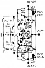
PSSR enhanced version
As the sea is rough today I found some time to draw PSSR enhanced version which already includes BIAS and OFFSET trimmer control in a simpler manner. Better PSSR is achieved by LM317/337 L series regulators (100mA output current version) enables -80dB ripple rejection on their outputs. Proper bias regulation is made by changing their output voltages symetrically and offset by balancing their output voltages according to GND. So only two TO-92 devices were implemented instead of zeners but with much more stable amplifier DC conditions and elegant BIAS-OFFSET control.
As the sea is rough today I found some time to draw PSSR enhanced version which already includes BIAS and OFFSET trimmer control in a simpler manner. Better PSSR is achieved by LM317/337 L series regulators (100mA output current version) enables -80dB ripple rejection on their outputs. Proper bias regulation is made by changing their output voltages symetrically and offset by balancing their output voltages according to GND. So only two TO-92 devices were implemented instead of zeners but with much more stable amplifier DC conditions and elegant BIAS-OFFSET control.
Attachments
Lazy Cat,
the worst thing one can do is to design the perfect amplifier in 24 hours. I would like to suggest this amplifier to remain simple and not deviate from the original design at all for now and allow it to evolve over time to become a great piece of audio equipment.
I believe you have sown a seed by offering something different and those building it will be very happy and those with the ability will come with suggestions, upgrades and improvements that can be implemented over time.
Nico
P.S. JHL and Higara's amps became classics and can be refined, but the originals remain just that originals. Not great specs but a music lovers amp
Last edited:
I do think the same as Nico.... i found second and third ideas
worse in the simulator....now more second harmonics...the first layout was the best one in the simulator..of course real world can be different.
I have just simulated the third one...this one you publish a few minutes ago...was the worst one in the simulator.
Well.. simulator does not play music....it is just numbers.
regards,
Carlos
- Status
- This old topic is closed. If you want to reopen this topic, contact a moderator using the "Report Post" button.
- Home
- Amplifiers
- Solid State
- Simple Symetrical Amplifier