
now more second harmonics...the first layout was the best one in the simulator..of course real world can be different.
More second harmonics, isn't that even better?

So that immediately tell us something, it looks we should leave 1k bias trimmer parallel with 100uF elco in function to stabilize +/-0,6V bias voltage of the input pair.
I think real listening tests will tell more ...
Last edited:
Ahaha I love this guy, his clips has been pretty usefull to me in the past, I seriously doubt he is an audiophile though, he strikes me as too no nonsense for the type.
Yep.... simulators only inform numbers.... this is really not enought
Sound is another thing as you know... there are many guys that believes in numbers.... i do not believe...i use numbers to have a good communication with the ones like numbers..but i really trust in listening tests.
Well....i am really busy doing other amplifiers, i hope someone give a try on this one and say something about.
If simulators could play music...distorting when distorted...increasing second harmonics, or third, or fourth...producing something we can trust...for sure would be lovely....maybe the future will bring this for us...but even this way will never substitute human ears, human feeling while listening...there are much more than music in that stuff..there are feelings...the communication with our souls that some amplifier can make ...and others not...this is not measurable.
Guys alike Hugh Dean when around an amplifier seems a lot to me.... this is a good sign about this design...also you Nico is around...this is another good sign....if people alike you are here...the amplifier may be very good.... when we see smoke.... well....must have fire around...when we see good guys around some amplifier is because it may be good.... these signs i respect... follow the good guys and we will have something good to listen.
regards,
Carlos
Last edited:
Yes digits.... he shakes me from time to time...he is really focused in technology
and we sometimes do not match his ideas....sometimes he is right...about this video i can agreed with him in almost 99 percent.
He loves Multimeters...also he has a very demanding mind about electronics...i do like he become upset with our audiophile world that has some exotic ideas...i feel him funny...i do like him.
Sometimes he shakes me...sometimes he shocks me... i use to be watching his video from time to time....i have some troubles to understand when he is being ironic or talking serious.
this Greek audiophile club video makes me laugh sometimes...it is a good reference to us, to think about the stuff.... avoiding us to loose contact with the reality.
regards,
Carlos
Lazy Cat, I should have mine done by tomorrow afternoon (my time) to give you my "subjective" review. What I would like if Alexmm is around is to add the power supply caps and rectifier on board thus making a nice amp with on-board power supply and it is only necessary to add a transformer.
Lazy Cat kindly draw Alex a schematic showing the non-electrolytic by-pass caps and maybe replacing the BFs with BCs. I would suggest four on-board 10A rectifier diodes and two 4700uF/63V caps.
Lazy Cat kindly draw Alex a schematic showing the non-electrolytic by-pass caps and maybe replacing the BFs with BCs. I would suggest four on-board 10A rectifier diodes and two 4700uF/63V caps.
Yes Nico, simple one PCB amplifier should also have all on board connections, that would make it even simpler, real beauty to DIY-ers.
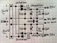
So I prepared quite standard power supply sch to be located together with amp on the same PCB. Connector for the transformer secondary AC in should be Phoenix type with screw wire fixation. Diodes could be other type, but certainly ultra fast recovery type to minimize on/off transition high frequency polution to the rails. Filtration is calculated to approximate power consumption of this specific amp, but can be altered or change accordingly to the best functionality.
So I prepared quite standard power supply sch to be located together with amp on the same PCB. Connector for the transformer secondary AC in should be Phoenix type with screw wire fixation. Diodes could be other type, but certainly ultra fast recovery type to minimize on/off transition high frequency polution to the rails. Filtration is calculated to approximate power consumption of this specific amp, but can be altered or change accordingly to the best functionality.
Attachments
After building a spider web mock-up, my first impressions were that it sounded very good, but after a while it fatigued me a little (listen on headphones HD800s, which is the easiest way to get irritable). Subjectively I would say that the odd order harmonics may be responsible as it sounds too crisp/detailed for my liking. Transients are excellent bass is very tight and probably due to the high bandwidth.
Lazy Cat, I made a few modifications to the circuit and I now appreciate your design much more. The mods evened out the harmonic artifact and the subjective sonic results are excellent (no measurements has been made this is subjective only)
I do not want to corrupt this thread with modifications as I have asked you not to and would like to ask if you would start a new thread calling for Simple Symmetrical Amplifier Updates, and I will post my stuff there.
Kind regards
Nico
Yes Nico, simple one PCB amplifier should also have all on board connections, that would make it even simpler, real beauty to DIY-ers.
So I prepared quite standard power supply sch to be located together with amp on the same PCB. Connector for the transformer secondary AC in should be Phoenix type with screw wire fixation. Diodes could be other type, but certainly ultra fast recovery type to minimize on/off transition high frequency polution to the rails. Filtration is calculated to approximate power consumption of this specific amp, but can be altered or change accordingly to the best functionality.
Per popular wisdom, your grounding is wrong. The main filter cap gnd should not be connected through the star point. They should have their own connection straight across, preferably with solid copper or aluminum bar, and then the center point of that goes to the star. Minor difference in your drawing, but it can be make a big difference to how a PS is wired or laid out on a PCB.
After building a spider web mock-up, my first impressions were that it sounded very good, but after a while it fatigued me a little (listen on headphones HD800s, which is the easiest way to get irritable). Subjectively I would say that the odd order harmonics may be responsible as it sounds too crisp/detailed for my liking. Transients are excellent bass is very tight and probably due to the high bandwidth.
Lazy Cat, I made a few modifications to the circuit and I now appreciate your design much more. The mods evened out the harmonic artifact and the subjective sonic results are excellent (no measurements has been made this is subjective only)
I do not want to corrupt this thread with modifications as I have asked you not to and would like to ask if you would start a new thread calling for Simple Symmetrical Amplifier Updates, and I will post my stuff there.
Kind regards
Nico
So first listening test took place, nice.
Nico I would really like to go on with this thread since it started as not fixed project but the project with evolving possibilities to come to the best solution around the basic core of the circuit and ready made PCB at the end. So any differences made are welcome and there is no need to start new thread, cause that would only bring a confusion. Let this thread finish the design started as a common DIY project, with your strong contribution. I hope you'll agree.
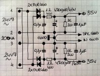
Per popular wisdom, your grounding is wrong. The main filter cap gnd should not be connected through the star point. They should have their own connection straight across, preferably with solid copper or aluminum bar, and then the center point of that goes to the star. Minor difference in your drawing, but it can be make a big difference to how a PS is wired or laid out on a PCB.
OK thanks AJ, corrected.
Attachments
Thanks Lazy Cat, attached please find my contribution in this regard. As I said the results at this point remains subjective and I will post the simulated results as reference.
Attachments
Hehehe, I am happy to hear that your listening impressions and simulated results are good. I experienced the same excellent musical enjoyments as you did, only with my BIGBT outputs present.
As I already stated before, clasical current feedback amplifier topology obviously needs buffer at the output and performs an order of magnitude worse if this one is missing.
Your SCH is fixed or it is discussable about some minor changes? Let's say about biasing regulation possibility, for someone to determine the level of quiescent current by himself.
Last edited:
OK so we are on line both.
Look, few comments:
- I would certainly omit cap at input
- bias regulation from A/B to A class
- feedback loop from the output, to better control load conditions
- maybe mosfet as I/V conversion and BJT as buffer
For now enough, please comment.
Look, few comments:
- I would certainly omit cap at input
- bias regulation from A/B to A class
- feedback loop from the output, to better control load conditions
- maybe mosfet as I/V conversion and BJT as buffer
For now enough, please comment.
I have looked at no input capacitor, problem is if input has dc off-set then the offset is transferred to output. Maybe all ancillary equipment is either capacitive coupled or has near zero off-set.
Yes I agree one could bias it class A, but AndrewT mention that it is very heat intensive and maybe needs a few parallel devices for output.
FB loop from output - of course this was a mistake when I drew it neatly, I will fix it. Simulation is correctly terminated.
Last point I do not understand what you mean.
Yes I know that perfectly, I want that the amp is DC coupled overall, maybe someone would use it for turntable DC motor or DC servo motor control, both direction linear regulation.
So no signal bypass caps.
I really didn't mean to put it in full power A class, but it certainly should have bias regulation, cause people found out that at certain bias level amplifier sounds the best, it somehow tracks Gauss distribution curve where you have quiescent current on X axis and pleasure factor on Y axis.
So bias regulation is mandatory.
FB loop from the output settled.
In my last request I meant to have mosfet transistor located as driver and powerful BJT as output device, vice versa as it is in your sch.
I think that mosfet by its nature belongs to this position as we can choose medium power mosfet driver having low Cgs, high forward transconductance, low drive energy for previous stage. BJT as the output device will perform excellent. Also this combination suits my BIGBT philosophy.
Last edited:
- Status
- This old topic is closed. If you want to reopen this topic, contact a moderator using the "Report Post" button.
- Home
- Amplifiers
- Solid State
- Simple Symetrical Amplifier