I need a BJT non-TT SSA to use with +-52V rails. I have some NJW4381/1302 to use up.
I just found a very nice chassis with a ~500VA or more transformer with dual 37 0 37 AC outputs. Only limitation with this is the PCB would have to be max 3" tall x 7" long to mount parallel on the thick chassis heatsinks to fit inside and not be too close to the transformer. Transistors would have to mount underneath the board, with holes in the board for screwdriver access.
I've got all the parts to build including PCB material, but I am not skilled enough to design an optimized PCB for this idea. I could use perfboard and try it worst case. Rectification and filtering could be done onboard or not.
Anybody in line with my thoughts? Any chance of that happening?
Not yet.
Until now three PCB's were made:
- post #224 dual mono PCB, Nico's version according to Nico sch, one pair 2SJ162/2SK1058 laterals
- post #227 single mono PCB, Alex's version according to Nico sch, one pair 2SJ162/2SK1058 laterals
- post #301 single mono PCB, Alex's version according to Miib sch, three pairs 2SJ162/2SK1058 laterals
There are quite a lot sch proposals and for an "all BJT's" version we have to make a consensus for the one Alex could possibly design as a thread request.
Please put down your suggestions which sch we should pick to make another PCB. My would be for the last one ...

Couldn't any version that contains the front end, be fairly easily grafted to the choice of output buffer? Maybe keep them separate?
Sheldon
This .....
"- post #301 single mono PCB, Alex's version according to Miib sch, three pairs 2SJ162/2SK1058 laterals"
or preferbly:
" it is even possible to double the number of output devices to handle below 1 ohm speakers"
Count me in for PCB's i have same issue ..direct drive...
"- post #301 single mono PCB, Alex's version according to Miib sch, three pairs 2SJ162/2SK1058 laterals"
or preferbly:
" it is even possible to double the number of output devices to handle below 1 ohm speakers"
Count me in for PCB's i have same issue ..direct drive...
At this case simm is wrong.
I extensively push hard the temp of the whole amp stages and there is none offset temperature dependency. I measured max deviation of +/-10mV DC at output pin, also explained this in some previous post already, so no DC servo required.
The simulation is right , mind you..
Pushing power with a non cased amp will do nothing since the thermal stability
is determined by the input stage wich is on a table , with no thermal
influence from the output stage thermal dissipation.
Once you put the whole amp on a case , things will be different and will be
quite correlated with the sims..
As a test, use a solder iron head close to one input device or both.....
Member
Joined 2009
Paid Member
Sheldon,
I just realized that you want to use the TT outputs because you have them on hand, I also want an all-BJT design but I don't have any TT outputs (unless you have spare !) so my needs for a pcb are really for non-TT devices.
I don't have any objection to designing my own pcb's and this might be easiest if I start with something that Alex draws up first - I believe he uses Eagle which is what I have access to.
Sheldon,
I just realized that you want to use the TT outputs because you have them on hand, I also want an all-BJT design but I don't have any TT outputs (unless you have spare !) so my needs for a pcb are really for non-TT devices.
I don't have any objection to designing my own pcb's and this might be easiest if I start with something that Alex draws up first - I believe he uses Eagle which is what I have access to.
I've got 4 of each flavor, so enough for four channels with a single pair each. I only need one stereo amp, so I have a spare set. I'm thinking, that with the cfp, hfe matching for the buffer drivers is not as critical. The extra gm that results should help linearize the output buffer. Or no?
Regarding cfp and compensation: Two diode drops per side, one for driver and one for output, are required for the spreader. Seems like one could use the TT diodes to track the outputs and two other diodes to track the drivers. Trial and error could maybe come up with a reasonably compensated and biased amp. Could always add a vbe multiplier, if necessary. This thread has good info: http://www.diyaudio.com/forums/soli...al-compensation-thermal-trak-transistors.html
Sheldon
Last edited:
Member
Joined 2009
Paid Member
Wow, that's very kind of you - I wasn't putting you on the spot I hope. Well, I actually need three channels - what I'm building is gonna power the front L, front R and front centre of my home theatre. I'm fussy about my HT set up and want a very good amp for it. I also use my HT set up for listening to music because the seating works well for stereo whereas in my living room, where I have my tube amp, the furniture is arranged to suit domestic needs...
With cfp the thermal stability is already more or less a non-issue - from what I have read. This is because the 'slave' device, which takes all the current in a CFP, is within the firm grip and control of the 'master' device that drives it - and as such can't easily head off into thermal issues. Since the 'master' device is operating at lower current and is away from the heatsink it shouldn't experience large temperature swings.
The bias string needs enough Vbe drops (4 as you say) to create enough idle current but that's a different question from how many diodes it takes to provide the right amount of thermal compensation.
Last edited:
Member
Joined 2009
Paid Member
looking into Thermal Trak:
Digikey no longer shows pricing for the NJL1302D device, just says 'call' - not a good sign.
At Mouser it says they have '150 on order' so none there.
Are these things getting enough demand to keep them in production I wonder.
Newark has a few, but $5 each.
Digikey no longer shows pricing for the NJL1302D device, just says 'call' - not a good sign.
At Mouser it says they have '150 on order' so none there.
Are these things getting enough demand to keep them in production I wonder.
Newark has a few, but $5 each.
I think they only sell them in tubes of 25.
Sheldon
edit: Mouser has njl0281/0302, which is even better - lower input cap.
Last edited:
Member
Joined 2009
Paid Member
26V rails work?
you may be another customer for the all-BJT version - since they allow you to swing the output closer to the rails than is usually the case with FETs. And at this power level you only need a single output pair. My TGM amplifiers have all been used with +/- 27V rails.
edit: I'll put my vote behind the single output pair too. It was where I started and it matches the needs of others. It's cheaper, runs cooler, easier to build and has adequate power for my HT project.
Last edited:
Member
Joined 2009
Paid Member
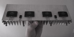
I scored a dead Onkyo amplifier, an old one. Lots of it seemed broken, including the power trafo so I decided to scrap it. But the heatsink looks handy. I'm wondering if it would serve for a 3-channel SSA. The amplifier was rated at 80W per channel = 160W total, which would mean 50W per channel for 3 SSA channels. Mind you, it would be a shame not to use the nice Sanken's already bolted in place.
Attachments
you may be another customer for the all-BJT version - since they allow you to swing the output closer to the rails than is usually the case with FETs. And at this power level you only need a single output pair. My TGM amplifiers have all been used with +/- 27V rails.
edit: I'll put my vote behind the single output pair too. It was where I started and it matches the needs of others. It's cheaper, runs cooler, easier to build and has adequate power for my HT project.
Is this due to higher gain of BJT vs Fets?
Member
Joined 2009
Paid Member
I was thinking about MOSFETs, which need around 4V to turn on, so you 'lose' 4v off each rail because of this. Rather than be lazy I looked up the data sheet for your LatFETs and they have a very reasonable turn-on threshold voltage which looks as if they would be fine with the rail voltages you propose.
The simulation is right , mind you..
Pushing power with a non cased amp will do nothing since the thermal stability
is determined by the input stage wich is on a table , with no thermal
influence from the output stage thermal dissipation.
Once you put the whole amp on a case , things will be different and will be
quite correlated with the sims..
As a test, use a solder iron head close to one input device or both.....
So you think I did not check?
The input pair BJT's must have the same hFE and zero ΔT, in that case offset cancellation after I/V conversion is in direct proportion to ΔIcn-ΔIcp, which is automatically zero regardless T value.
The unique SSA's current feedback loop (bridge) has some specially good features still not really understandable to all ...
Member
Joined 2009
Paid Member
I'd like to ask those who have been simulating this amp can post it so I can play with myself that would be great. I'm wondering if the simple version might be up to the task if I'm only after 60W peak output ?
The simplest all-BJT version is post 183, which uses double EF output.
Post 336 with Single o/p pair would be simplest option with CFP driver but it's quite a few extra devices.
Comparing these two options how much benefit would we see with CFP drivers into 6 Ohm load (let's pretend 8 Ohm speakers have nasty dips) at 60W peak power ?
p.s. can anyone tell me what is the open loop gain (e.g. on +/-36V rails with conventional level of input sensitivity).
Last edited:
- Status
- This old topic is closed. If you want to reopen this topic, contact a moderator using the "Report Post" button.
- Home
- Amplifiers
- Solid State
- Simple Symetrical Amplifier