Can somebody please tell me or measure what the voltage is on:
C6 47uF voltage=
C8 47uF voltage=
C11a 220uF voltage=
C11b 220uF voltage=
The transformer you use must be 2 x 42 volts or more.
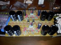
I have 100V ELNA SILMIC II Audio Capacitorcaps, but they don’t fit on the board, and maybe I can put in 63 volt types.
Regards,
Rudy
C6 47uF voltage=
C8 47uF voltage=
C11a 220uF voltage=
C11b 220uF voltage=
The transformer you use must be 2 x 42 volts or more.
I have 100V ELNA SILMIC II Audio Capacitorcaps, but they don’t fit on the board, and maybe I can put in 63 volt types.
Regards,
Rudy
I buy it as sheets which is much cheaper than precut shapes. I just cut the needed sizes myself, works a charm")
Well, one shop here in Dubai is selling 500 pieces(pre-cut) in a pack, which cost me 50 dirhams that's approximately USD14.00
Hey Junito! where did you get those so many damn!
regards
vargasmongo3435
Amigo Juan, arrange a pick-up collection and I will send you some for free
Hi Rudy, I used 100V in on those caps since my supply voltage is +73v-0v-73v, I cannot find 80V though otherwise I will use it.
Please make a close-up picture
I have 100V ELNA SILMIC II Audio Capacitor caps, but they don’t fit on the board.
The diameter of the caps on the board must be.
47 uF is 8 mm
220 uF is 10 mm
100 uf is 8 mm
And this is very small
Regards,
Rudy
Last edited:
Nice Juan ...thank you
Audio now is much better....i am uploading video explaining you how to filter a little bit more.
Saturday night having fun with MKIII Hx and my petz - YouTube
Here an idea to you hermano:
http://www.youtube.com/watch?v=rfvkfCZW7K8
regards,
Carlos
Audio now is much better....i am uploading video explaining you how to filter a little bit more.
Saturday night having fun with MKIII Hx and my petz - YouTube
Here an idea to you hermano:
http://www.youtube.com/watch?v=rfvkfCZW7K8
regards,
Carlos
Last edited:
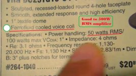
MKIII Hx is a high power amplifier...this may look great
but also big will be the problems this will create to speakers...they usually are not rated to so huge power.
Observe the chart of power (specifications) published in this thread, in the group buy thread and also in the MKIII thread...there you have power to several output impedances correlated to transformer power.... so, observe the power you will have as a result of your impedance and your transformer.
Knowing your power..then select your speaker driver's this way:
60 percent of the total power will go to the woofer
30 percent of the total power will go to the midrange driver
10 percent of the total power will go to the tweeter driver
This is the normal distribution of power you will perceive inside commercial speakers...a 100 watts speaker uses a 60 watt woofer, a 30 watt midrange and a 10 watt tweeter...this is the normal, to save money in the production line.
So, knowing your power you can know your needs about speaker rating.
The first trouble is that when you clip your amplifier...and people does that without perceive.... some modern music are already clipped, or distorted in the master.... then harmonics will be generated because the square wave...and all harmonics will be a bomb thrown into the tweeter that usually is the first that gonna die.... then knowing that, use 4 tweeters, the power rating will be very high, as you gonna add four tweeters power rating and also the series resistance used to reduce the HIGHER ACOUSTIC PRESSURE that is consequence of 4 drivers playing instead of a single one...use series parallel..two tweeters in series together other two tweeters in parallel... a series resistance will go from 16 to 32 ohms in order to balance the sound to result acoustically flat or flat to your ears.
Here is my friends video that create me panic..... that tweeter would die easy and fast...MKIII Hx can put out several amperes..it is an eartquake!
Nani destroy my woofers magazine - YouTube
And here my comments about the ferrofluid fashion thing:
- "The idea may be fine...that tweeter is fine...but the ferrofluid cooling is not a good idea as that oil damps the tweeter, it is a sticky grease thing surrounding the coil that damps the movement..it cools down, that oil helps..but sonics will not be all that brigth because the sticky thing...try another model, , air cooled, soft some, silky dome, lightweigth dome, but avoid the ferrofluid. knowing your supply power we can know power..tweeter is 10 percent total power... 30 watts tweeter is good to 300W amp"
You have a picture about too.
regards,
Carlos
Attachments
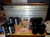
Hello everyone,
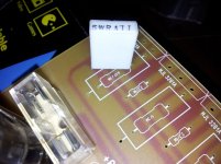
I have now almost all parts but still have a few questions and hope that I get an answer, because it is confusing what I read on the printed board and the part list.
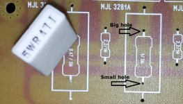
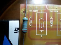
Also the R26 A to J, 0R47 5 Watt non inductive resistors only fit on one side, the hole is to small on 1 side see picture
Have 20 new 2R2 0.25 watt resistors purchased because the 1 watt resistors were too big, they do not fit in the holes of the print.
Is it wise to use 0.25 W resistors for R24 A to J 2R2 because there on the printed board I read 1 Watt??
Now it is these resistors, they are in part list:
R27 2 pieces 10R 5 Watt --à I can’t find them on the board
R28 2 pieces 15R 3 watt. --à I've tried and 1 watt did not fit in the holes of the print, what wattage I need for this one?
Please tell me what the right wattages are for those resistors R27 / R28 / R24 A to J.
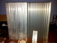
And YES, the heat sinks arrived this week for testing, maybe I need bigger ones we will see, only the aluminum blades are on the wrong side
What is the best way to screw thread tapping into aluminium
Regards,
Rudy
I have now almost all parts but still have a few questions and hope that I get an answer, because it is confusing what I read on the printed board and the part list.
Also the R26 A to J, 0R47 5 Watt non inductive resistors only fit on one side, the hole is to small on 1 side see picture
Have 20 new 2R2 0.25 watt resistors purchased because the 1 watt resistors were too big, they do not fit in the holes of the print.
Is it wise to use 0.25 W resistors for R24 A to J 2R2 because there on the printed board I read 1 Watt??
Now it is these resistors, they are in part list:
R27 2 pieces 10R 5 Watt --à I can’t find them on the board
R28 2 pieces 15R 3 watt. --à I've tried and 1 watt did not fit in the holes of the print, what wattage I need for this one?
Please tell me what the right wattages are for those resistors R27 / R28 / R24 A to J.
And YES, the heat sinks arrived this week for testing, maybe I need bigger ones we will see, only the aluminum blades are on the wrong side
What is the best way to screw thread tapping into aluminium
Regards,
Rudy
Attachments
Last edited:
Bimmer, many hole are too small... You will need to enlarge them. Luckyli for me, being a hobbyist I had many small drill bits and a hand driver. Look for drill bits that are numbered (not in fraction of inches nor in millimeters, but really numbered) See this chart: CHART_PDF. Hobby shops (model train, etc.) have them.
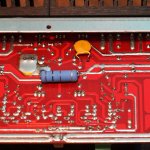
For the 10R 15W, they're in parallel with the output air-cored coil. It should be soldered under the board (don't include them in the coil as this will change the inductance value).
Martin.
For the 10R 15W, they're in parallel with the output air-cored coil. It should be soldered under the board (don't include them in the coil as this will change the inductance value).
Martin.
I didn't meant 15W but 5W... See this pic below for my installation of it.
For taping into aluminium, make sure you got the correct drill bit size, and ABSOLUTELY get yourself some aluminium cutting oil. There are many charts on the net for the drill bit size vs tap size. You want to find a specialized shop where they sell machine-shop tooling for that.
Put cutting oil on the drill bit and a drop on the surface to be cut, use a drill press, it helps make the holes perfectly perpendicular to the plane.
When taping, make 1/2 turn foreward, then do 3/4 turn backward, then go 1/2 turn deeper, then back 3/4 turns and so on. Put cutting oil in the hole and also on the drill bit with a hobby paint brush.
Cutting oil makes difference between success and a stuck-and-then-broken tap, which is a PITA. BTDT
See this pic below for my installation of it.For taping into aluminium, make sure you got the correct drill bit size, and ABSOLUTELY get yourself some aluminium cutting oil. There are many charts on the net for the drill bit size vs tap size. You want to find a specialized shop where they sell machine-shop tooling for that.
Put cutting oil on the drill bit and a drop on the surface to be cut, use a drill press, it helps make the holes perfectly perpendicular to the plane.
When taping, make 1/2 turn foreward, then do 3/4 turn backward, then go 1/2 turn deeper, then back 3/4 turns and so on. Put cutting oil in the hole and also on the drill bit with a hobby paint brush.
Cutting oil makes difference between success and a stuck-and-then-broken tap, which is a PITA. BTDT
Attachments
Last edited:
Thanks canonnica for the replies but still have a few questions
1. R28 2 pieces 15R 3 watt. I've tried and 1 watt did not fit in the holes of the print, what wattage I need for this one?
2. Have 20 new 2R2 0.25 watt resistors purchased because the 1 watt resistors were too big, they do not fit in the holes of the print.
Is it wise to use 0.25 W resistors for R24 A to J 2R2 because there on the printed board I read 1 Watt??
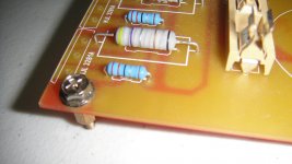
Because "I see 0.25 watt" on the pictures to other builders?
On the second picture you see 1 watt.
Regards,
Rudy
1. R28 2 pieces 15R 3 watt. I've tried and 1 watt did not fit in the holes of the print, what wattage I need for this one?
2. Have 20 new 2R2 0.25 watt resistors purchased because the 1 watt resistors were too big, they do not fit in the holes of the print.
Is it wise to use 0.25 W resistors for R24 A to J 2R2 because there on the printed board I read 1 Watt??
Because "I see 0.25 watt" on the pictures to other builders?
On the second picture you see 1 watt.
Regards,
Rudy
Attachments
Last edited:
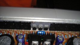
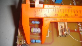
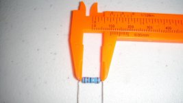
Size of the 2.2 ohms I use 1/2W
Hey bro!
Well I'm using 0.5 watts resistors but also you can use 0.25 watts, I'm using 1/2 watt just for insurance the size of the resistor I'm using is about 10mm, and since is a bit bigger than the silk screen you have to bend it a little closer to the resistor frame, maybe this will help.
regards
vargasmongo3435
Attachments
Last edited:
- Status
- Not open for further replies.
- Home
- Amplifiers
- Solid State
- Dx Blame MKIII-Hx - Builder's thread