The resistor with value of 47kohm should be lower. Try with lower values 39k,33k,30k.... to voltage drop across 5W resistors are 2A=voltage drop/ resistor value. With 2A current you will have 36W/8ohm on pure class A.
The resistor's value 0.47ohm 10W is large. Try with 0.22ohm. Lower value of this resistor should improve the bass control.
The resistor's value 0.47ohm 10W is large. Try with 0.22ohm. Lower value of this resistor should improve the bass control.
Hello
I built a couple Hiraga Class A with different rail voltage. Never so high like 28V or 35V etc. To me that absurd! One pair power transistor can't take that much heat fully Class A bias! No way!!!
At least I don't know such a transistor was produced to audio purpose. Can be some company special design but I don't know about if it would be assailable for DIY purpose.
30W more than enough in Class A at normal listening level (home use)
To write some info the bias set up
There is two important think you must take care!
One the diode V rating!
Second the 47K resistor in your case! But think, if Dan uses the same Voltage and 47K resistor you have some other problem. The driver transistors lightly warm even under heavy load to..
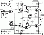
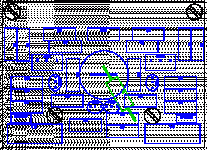
Take a look these two parts how it change when you use different rail voltage.
I built the 13V diode version- I would never ever try again
I built two 20 and 22V version and bot work and sounded great.
I'll build it again with better component.
The high voltage version can't be biased in a full Class A mode but who need that risk (you newer know when the power transistor trow the towel in and take out your woofer)
I would not even try to build that!
If you need high power Class A amplifier (because your speaker power hungry) build some N Pass Aleph amplifier like 2, 4, or 5.
If you prefer transistor sound go with A40.
Again with 24V you can get 30W. That must be enough for a normal size living room to drive even 84-85db speakers!
These is the problem when someone built something different (out of the ordinary)and we try to copy that but different rail voltage.
I believe with the 35V rai voltage Dan did his home work to until everithing was set up and get out the right compromisum.
With that high voltag you must have some compromisum like not full Class A bias, change the power transistors often so on...
Please study the diode and the resistor value at different rail voltage.
13V to me worked but sounded awfull.
20 and 22 was nice.
I can't comment different voltage.
I marked the resistor responsible for the bias! But the diode to!
I hope these help!
The 19-20V is the 20W , the 24V is the 30W..
Start with low bias and increase it. Pay att. do not fry the transistor. After you set up the amp chek it with your tumb 10 second min.
At the begining check it every 5-10 minutes or so after every 30 min..
Greetings Gabor
I built a couple Hiraga Class A with different rail voltage. Never so high like 28V or 35V etc. To me that absurd! One pair power transistor can't take that much heat fully Class A bias! No way!!!
At least I don't know such a transistor was produced to audio purpose. Can be some company special design but I don't know about if it would be assailable for DIY purpose.
30W more than enough in Class A at normal listening level (home use)
To write some info the bias set up
There is two important think you must take care!
One the diode V rating!
Second the 47K resistor in your case! But think, if Dan uses the same Voltage and 47K resistor you have some other problem. The driver transistors lightly warm even under heavy load to..
Take a look these two parts how it change when you use different rail voltage.
I built the 13V diode version- I would never ever try again
I built two 20 and 22V version and bot work and sounded great.
I'll build it again with better component.
The high voltage version can't be biased in a full Class A mode but who need that risk (you newer know when the power transistor trow the towel in and take out your woofer)
I would not even try to build that!
If you need high power Class A amplifier (because your speaker power hungry) build some N Pass Aleph amplifier like 2, 4, or 5.
If you prefer transistor sound go with A40.
Again with 24V you can get 30W. That must be enough for a normal size living room to drive even 84-85db speakers!
These is the problem when someone built something different (out of the ordinary)and we try to copy that but different rail voltage.
I believe with the 35V rai voltage Dan did his home work to until everithing was set up and get out the right compromisum.
With that high voltag you must have some compromisum like not full Class A bias, change the power transistors often so on...
Please study the diode and the resistor value at different rail voltage.
13V to me worked but sounded awfull.
20 and 22 was nice.
I can't comment different voltage.
I marked the resistor responsible for the bias! But the diode to!
I hope these help!
The 19-20V is the 20W , the 24V is the 30W..
Start with low bias and increase it. Pay att. do not fry the transistor. After you set up the amp chek it with your tumb 10 second min.
At the begining check it every 5-10 minutes or so after every 30 min..
Greetings Gabor
Attachments
Last edited:
Hello
You right, probably it would be better.
But first I want to help him to set up his amp (at least to get some life or sound).
I think if He use all the same component after Dan's schematic it must be problem with some of the semiconductor(s)
Can be the power transistors, do you have any offset? Can you measure any +/- voltage on the power transistors?
Do the drivers and the signal transistors are at the right place, check their pin out to.
These amp so simple it must work!!
That is the minimum, a 12 year old boy can build these amp.
There is a mistake somewhere that is sure.
Please look up on the net all the transistor pin out E-C-B and follow the schematic not the lay out!
Please check if all PNP and NPN transistor if are at the right location.
Measure all the transistors for shortage or open to.
Greetings Gabor
Hi, everybody
There is some sound actually,you know? but the output stage transistors dont get warm at all and the driver transistors run quite hot.Garbor,what transformer secondery do I need to obtain the voltage rail that you suggest? Bytheway my zeners are 22v.Is it possible to drop the volltage with other choice of zeners?
Greetings, Ashkan
Last edited:
Hello ash
How much (sound) power you get?
Please use a Digital MM and measure on the power transistor DCV to the ground. Please let me know what you get on E, C, B. Disconnect your speaker when you measure or do some adjustment!
To me both the driver transistors and the power transistors are suspicious to!
Toshiba long time (15 years) does not produce 2SC5200 and it's complementary parts.
Also 10 years a go when I used those NEC driver transistors it was hard to get them.
If you have at hand MJL21193/94 or MJ0281A/3281A ON semi for power transistors or if you can use metal case please use MJ15003/04 or MJ15022/23
Honestly I had all the orig NEC orig. transistors and after I tested the MJ11022/23 for power and MJE15030/31 driver transistors I sold the orig NEC transistors on Ebay.
I get more punch, deeper and controlled bass, cleaner mid range. Over all I got a lot of improvement with the ON semi transistors in every way.
Pay att. the driver transistor in (TO220 case) has different pin out.
To get 24VDC you must use 20VAC but use min 500VA rating for a stereo (2 channel)
The 22V Zener is OK.
Pleas use solid wire to connect the power transistors! I see your power transistors not soldered direct in to the PC board.
Greetings gabor
Hello Gabor
2SA634; B 33.5, C -11.3, E 34.3 \ 2SC1096; B -33.5, C 13.8, E -24(other channel -34) \ 2SC5200; B -11.2 , C 34.5 , E 0.3 \ 2SA1943 B 13.8 , C -24.5 ( other channel + 2.2) , E 0.3
Hello
If you use color coded resistors at first check them all if all value at the right place.
If not color coded to make 100% sure please remove one side (one pin) all resistor from the PC board where you have problem and measure all of them.
Be careful sometimes one resistor like (for example)2.2K exchanged with 22K mess up all your circuit.
After you check all of them soldered it back and change all the semiconductors from the good PC board to the one has problem.
I think (99% sure) one side (in one PC board) of your power or driver transistor or both are bad .
Also you can not have in one side -voltage other side + voltage. Is a mistake somewhere there!That mean one or more transistor is open (bad)
Greetings Gabor
Last edited:
Hi, Gabor. I checked all the resistors. every thing is allright. but there must be a serious problem maybe with the pcb itself . I am going to rebuild the amp with a new pcb (probably the one that you suggested earlier in this thread ) and the semi conductors that you suggested . but is it essential to replace the transformer first ?and if I am going to use the metal body transistors , do I have to replace the haet sink or it is possible to put the transistor on an extra piece of aluminum and then attach it to the existing heat sink ? (remember that there are holes in the enclusor and the tranistors are now attach directly to the heat sink).
thank you
Ashkan
thank you
Ashkan
Hello
That PC boar was tested by me to and work! The transformer very important when we build a Class A amplifier!
There is a minimum VA rating req. to achieve acceptable sound.
I used 500VA 20VAC and the transformer was warm, but safe.
Your heatsink another problem. Do you have 2PC or min. 1PC more like that?
I advise if you have cut them (use machine saw) half and mount them horizontally so the air can travel freely from buttom up.
Another possibility leave the heatsink like how they are now and use a 12V computer fan each side run them on 9V or so so not to get less noise.
But count on it you still get some noise.
I see at German Ebay someone good quality Hiraga Class A PC board, cheap and very nice.
Leer PCB Super Class A Verstärker Hiraga "L Audiophile" | eBay
If not to big investment to you get a pair. It look like you can use TO247 (like your Toshiba)transistor direct soldered in to the PC board. But buy some ON semi transistors, be sure not fake.
Be careful with Motorola transistors also.
Greetings Gabor
Last edited:
Hello
That PC boar was tested by me to and work! The transformer very important when we build a Class A amplifier!
There is a minimum VA rating req. to achieve acceptable sound.
I used 500VA 20VAC and the transformer was warm, but safe.
Your heatsink another problem. Do you have 2PC or min. 1PC more like that?
I advise if you have cut them (use machine saw) half and mount them horizontally so the air can travel freely from buttom up.
Another possibility leave the heatsink like how they are now and use a 12V computer fan each side run them on 9V or so so not to get less noise.
But count on it you still get some noise.
I see at German Ebay someone good quality Hiraga Class A PC board, cheap and very nice.
Leer PCB Super Class A Verstärker Hiraga "L Audiophile" | eBay
If not to big investment to you get a pair. It look like you can use TO247 (like your Toshiba)transistor direct soldered in to the PC board. But buy some ON semi transistors, be sure not fake.
Be careful with Motorola transistors also.
Greetings Gabor
I would not recommend these boards. I bought them but they are too small to accomodate 'High-end standard' components + some other issues. I Will use them as breadboard for tests and make my own.
OK I didn't knew that.
You can use the Stig Eric (design) I posted somewhere at the front. Many thanks to Eric!!!
Just do not forget you need 4 jumper for that PC board.
It is a great design and good upgrade over the original.
Greetings Gabor
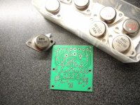
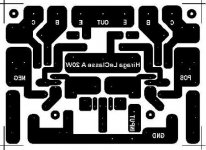
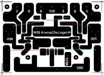
Curent issues, power issues, thermal issues ... Better to use 1/2W or even one watt resistors even if calculated 1/4 is enough. Better to use thicker copper or solder solid core on power rails and output Xtors.
Pix attached to have a better idea!
Curent issues, power issues, thermal issues ... Better to use 1/2W or even one watt resistors even if calculated 1/4 is enough. Better to use thicker copper or solder solid core on power rails and output Xtors.
Pix attached to have a better idea!
Attachments
Hello
Yes that PC board way to small. Probably it has other issue to how you mentioned.
The driver transistor just need a small heatsink but OK with out heatsink to. To spread the heat better you can use 1Cm copper over the aluminium heatsink (under the transistors) but very expensive.
The Erik design has very good lay out!
Greetings Gabor
Hello
Yes that PC board way to small. Probably it has other issue to how you mentioned.
The driver transistor just need a small heatsink but OK with out heatsink to. To spread the heat better you can use 1Cm copper over the aluminium heatsink (under the transistors) but very expensive.
The Erik design has very good lay out!
Greetings Gabor
I could not find Erik's one. But the original one on page 44 is good!
Note: it is better to buy all the best components you can buy first and then make the board. It is easy to do a good one even by hand!
Also, in my opinion, building this amp only makes sense if you have all the original active parts. (I will also try the 2sa1302 - 2sc3281 for the output)
Hello
Here you have
Whith these PC boar you can use 1W resistors to. It has room enoug some place even for 2-3W.
Greetings
Here you have
Whith these PC boar you can use 1W resistors to. It has room enoug some place even for 2-3W.
Greetings
Attachments
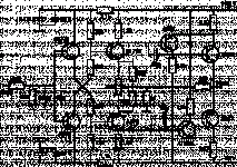
Those colored marks on the layout jumpers!
I used Capacitance multiplier power supply from ESP site.
For large caps I used 60 000 Mepco, the 470 use Philips/BC Axial or ROE, for 1000uF I used 2200Uf Rifa
Soft start must, otherwise you kill the power transformer very fast.
Greetings Gabor
I used Capacitance multiplier power supply from ESP site.
For large caps I used 60 000 Mepco, the 470 use Philips/BC Axial or ROE, for 1000uF I used 2200Uf Rifa
Soft start must, otherwise you kill the power transformer very fast.
Greetings Gabor
- Status
- This old topic is closed. If you want to reopen this topic, contact a moderator using the "Report Post" button.
- Home
- Amplifiers
- Solid State
- Hiraga 20W class A