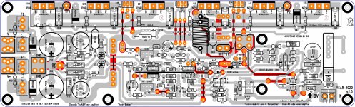
Yes its not an official Badger but its a clone made by vargasmongo who used the pdf that was released.Almost seems as NFB is being taken from the wrong point.
BTW , that is not an official Badger .
OS
Almost seems as NFB is being taken from the wrong point.
Yes, although feedback from the wrong point would cause dominant even harmonics, not odd harmonics. After the inductor the 2nd harmonic only increases by 1.78x whereas the 3rd harmonic increases by 56x. The near absence of 2nd harmonics strongly points toward magnetic saturation or a nonlinear resistor.
Yes, although feedback from the wrong point would cause dominant even harmonics, not odd harmonics. After the inductor the 2nd harmonic only increases by 1.78x whereas the 3rd harmonic increases by 56x. The near absence of 2nd harmonics strongly points toward magnetic saturation or a nonlinear resistor.
So a part ? Bad sourcing ? It can happen.
OS
No worries. Here are the pictures.Show the whole board . Top and bottom.
Im not saying I did an awesome job 8 years ago , but your issue is
unique. As is your board. But a board (or part) can be fixed.
A bad part , maybe not all boards would have the problem.
I have built 3 amp modules and they all exhibit increased distortion at 16khz
OS


Can you test the load resistor with the LCR meter to see how inductive it is?
No worries.
At 100hz 15uH Q 0.001
At 120hz 14uH Q 0.001
At 1Khz 12.4uH Q 0.009
At 10khz 12.23uH Q 0.094
At 100Khz 11.988uH Q 0.884
Dc resistance
8.08 ohms
AC resistance
8.08 ohms at 100hz
8.08 ohms at 120hz
8.088 ohms at 1Khz
8.102 ohms at 10Khz
8.495 ohms at 100khz
View attachment 935550
Wow, I guessed 15uH. Not bad. Maybe it's wirewound then. The drop in inductance at HF implies something metal shorting the inductor flux, which could be the aluminum case or perhaps mounting hardware or the tube the resistor is wound on.
In any case the 15uH is high enough it adds 1.88 ohms to the impedance at 20KHz, so I would prefer a low-inductance wirewound resistor for audio testing.
Here are the PCBs I found from Vargasmongo which show the layout:
diyAB Amp The "Honey Badger" build thread
In any case the 15uH is high enough it adds 1.88 ohms to the impedance at 20KHz, so I would prefer a low-inductance wirewound resistor for audio testing.
Here are the PCBs I found from Vargasmongo which show the layout:
diyAB Amp The "Honey Badger" build thread
Attachments
In any case the 15uH is high enough it adds 1.88 ohms to the impedance at 20KHz, so I would prefer a low-inductance wirewound resistor for audio testing.
Thank you for taking a look so promptly Keantoken. I do appreciate it.
How did you calculate the 1.88ohms?
Got it...
Do you have a supplier or part number that you could recommend?
View attachment 935553 View attachment 935554
Last edited:
So a part ? Bad sourcing ? It can happen.
Well if it is the load resistor, then it's not really the amp's fault. We are just seeing the expected consequence of the amp's finite output impedance driving a nonlinear load.
Stuart can test the amp with a different resistor load and he can try relocating the inductor.
Thank you for taking a look so promptly Keantoken. I do appreciate it.
How did you calculate the 1.88ohms?
Got it...
Do you have a supplier or part number that you could recommend?
Your last 3 attachments are nowhere to be found.
Inductive reactance is 2pi*F*L. 6.28*20k*15uH = 1.88ohm. Your meter was measuring resistance only, not impedance which includes resistance and reactance. The resistance increased with frequency which I suspect was due to skin effect or eddy currents in the aluminum shell.
Unfortunately I have no idea how to get non inductive high power wirewound resistors at an affordable price, which is why I don't have any. I'm very envious of your lab setup, I just have DMMs and analog scopes and my computer soundcard.
I did get some EBG UXP-350 resistors from Ebay which have been good enough so far, but I think still have some distortion.
Last edited:
I did get some EBG UXP-350 resistors from Ebay which have been good enough so far, but I think still have some distortion.
No sure what happened to the attachments.... all good. Thanks for verifying the Math.
I did pull out my inductor and measured it. 1.6uH so I trimmed of one coil and it measured spot on 1.5uH I reinstalled it under the pcb as a test. It did appear to reduce the distortion measured Across the load from 0.23% to 0.19% everything else remaining equal.
I also ran a test at the point before the inductor at 1k.... wow.... distortion dropped from ~0.00310% to ~0.00055% which is basically the loopback distortion levels.... wow....
Now I need to sort this output distortion.
I do have two 4 ohm resistors like the 8 ohm one so I guess that, as a test I could measure the distortion using a single 4 ohm load resistors then put the two of them in series and my other 8 ohm in parallel which would give me 4 ohms again but half the inductance.
What do you think about changing the output emitter resistors to 0.1 ohms so the output impedance is lower?
What do you think of this load resistor
284-NHS200-8.0F
https://au.mouser.com/access/?pn=28...m_campaign=284-NHS200-8.0F&utm_content=Ohmite
I see those ones you have on ebay but can't find a 8 ohm one.
Thanks again for your help.
I'll look again tomorrow at non inductive chassis mount resistors.
I wouldn't worry about the load inductance for now, it's more of a distraction.
There's not much to gain from reducing the emitter resistors although it is an option. Best to wait until after the distortion is sorted out.
I got the 8ohm ones while they were available on Ebay, I guess I was lucky.
I think I actually have one of those resistors, but one of the ends cracked and I seemed to be getting lots of distortion with it. I was pushing it too hard probably because I had nothing else at the time. I stopped using it because of the distortion issue but I may revisit it to make sure.
Stringing resistors together will reduce the load on each of them so presumably you will get lower distortion. It's worth a try.
You could also scavenge nichrome wire from an old heater...
Keantoken, just to check a few things and confirm my understanding of how this 12uH of inductance in the load resistor is possibly causing the problem.
So from what I understand the 12uH of Inductance is causing an extra 1.88 ohms of resistance as the sine wave is moving through the zero crossing and to the peek. So the load resistance is constantly changing from 8 ohms to call it 10 ohms. This coupled with the fact that an inductor opposes the initial flow of current while at the same time returning some current flow as the input current decreases. These two non ideal properties are causing the non linearity in the voltage measured across the load resistor.
Is this correct?
No. An inductor responds to the rate of change of the current. The rate of change of a sine wave... is also a sine wave at the same frequency. Therefore ideal inductors don't generate harmonics or distortion. The frequency dependence of their impedance is sometimes considered a linear distortion if it is undesirable. Reactive loads shouldn't cause any extra distortion in a class AB amplifier either except by increasing the load current as in the case of a capacitive load at HF.
The inductance is only of interest to us in identifying the mechanism of distortion if it lies in the load resistor. If the inductance changes depending on current, as is the case in magnetic saturation, then the inductance component of the load resistor will generate harmonics.
You don't need to worry about the exact cause as the solution is most likely to just get a different resistor. That's why I said the inductance is a distraction. We haven't confirmed whether the load resistor is the culprit yet, and that needs to come first. Then maybe there are ways to modify it to reduce the distortion.
The fact that your load resistor is inductive indicates it is wirewound which is actually an argument against it being a source of distortion. So things are still a bit weird.
This makes sense if you know the distortion mechanisms of resistors. In film and composition resistors, it is voltage coefficient. The resistance drops as voltage increases due to current jumping across grain boundaries. This behavior is not frequency dependent.
If it is wirewound there are no grain boundaries, so the only other explanation I see is ferrous mounting hardware causing the inductive component to generate harmonics. But this might just be my crazy conspiracy theory. Maybe the resistor even uses steel wire and that is why it is so cheap?
In any case since you don't seem to have an alternate resistor you can try locating the coil remotely with a twisted pair, and if that doesn't work it supports the theory of the load resistor being nonlinear.
Last edited:
Wow.... thank you @keantoken for all that useful information. I certainly didn't know that. Much appreciated that for sure.
So I did run another few tests with the resistors that I have and found that running;
1. A single 4 ohm resistor gave me 0.1%
2. A running two 4 ohm resistor in series also gave me 0.1%
3. A single 8 ohm resistor as before gave me 0.23% as it did last night.
4. Two 4 ohms in series and one 8 ohm in parallel (total 8 ohms) gave me 0.25%
Please also note that each 4 ohm resistor had an inductance of 7.5uH so when they were in series and we had 8 ohms there was also ~15uH. But only 0.11% distortion. Basically half.
So I guess the magnetic fields caused by the inductance weren't as strong given only 7.5uH so the weren't causing as much harmonics.
"the inductance component of the load resistor will generate harmonics"
I did also try running the load far away by extending my speaker cabling. Approximately 1.5m. This made no difference to the distortion measurements.
It seems like the 8ohm resistor has higher distortion than the 4ohm. To produce 2x the distortion it would have to have a 4x higher voltage coefficient.
If the distortion were due to the output coil it would correlate with load current. But you tried multiple 4 ohm loads and the distortion was different with different resistors.
If the distortion were due to the output coil it would correlate with load current. But you tried multiple 4 ohm loads and the distortion was different with different resistors.
I looked a getting this non inductive one made locally here today.It seems like the 8ohm resistor has higher distortion than the 4ohm. To produce 2x the distortion it would have to have a 4x higher voltage coefficient.
If the distortion were due to the output coil it would correlate with load current. But you tried multiple 4 ohm loads and the distortion was different with different resistors.
They are getting back to me with the exact inductance.

Can the end terminals be nonmagnetic?
I just checked some of mine of a similar style and the terminals are actually steel, must be why I wasn't using them anymore.
EDIT: They look like generic steel terminals:
Wire Wound Resistor Range — Cynebar
It's surprisingly difficult to get a high power wirewound resistor without some part made of steel. A lot of them use stainless steel wire.
Last edited:
I'll definitely look into that point.Can the end terminals be nonmagnetic?
I just checked some of mine of a similar style and the terminals are actually steel, must be why I wasn't using them anymore.
EDIT: They look like generic steel terminals:
Wire Wound Resistor Range — Cynebar
It's surprisingly difficult to get a high power wirewound resistor without some part made of steel. A lot of them use stainless steel wire.
Thank you.
- Home
- Amplifiers
- Solid State
- diyAB Amp - The "Honey Badger"