
more
attached files show the potential of new amp...
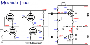
the idea comes from John Broskie and his TCJ Moskido I-out More Current-Output Amplifiers
This is not new idea:
http://www.semigor2.narod.ru/superA.html
Attachments
Padamiecki this page might hold some interest for, look at the third circuit.
Only Distortion Negative Feedback Circuit
Only Distortion Negative Feedback Circuit
Thank you for this very interesting URL
English please Semigor.
diyaudio translate the URL
http_www.semigor2.narod.ru_superA.html
in the subtitle of the associated website.
Thus nobody haven't any influence regarded its language except the owner of this website.
Last edited:
Padamiecki this page might hold some interest for, look at the third circuit.
Only Distortion Negative Feedback Circuit
I don't see anything here that is not classical feedback, only differently arranged.
Classical feedback says that distortion approaches zero if beta*Aol approaches infinity.
That is exactly the condition in this article, with Aol replaced by K*D. Same thing.
jan
Padamiecki this page might hold some interest for, look at the third circuit.
Only Distortion Negative Feedback Circuit
I knew this site,
what I wanted to show
is an interesting output circuit with grounded sources/emmiters.
This of course makes relatively high output impedance
but
this makes current output which sounds so good (only peak resonances of the woofers/tweeters have to be dumped)😉
At this output stage you can adjust between grounded emitter and emitter follower:I knew this site,
what I wanted to show
is an interesting output circuit with grounded sources/emmiters.
This of course makes relatively high output impedance
but
this makes current output which sounds so good (only peak resonances of the woofers/tweeters have to be dumped)😉
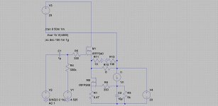
Ultra low on resistance MOS-FET 2SK1595 classA single power amplifier
At this output stage you can adjust between grounded emitter and emitter follower:
Ultra low on resistance MOS-FET 2SK1595 classA single power amplifier
this one I forgot but looks very promissing,
thank you
At this output stage you can adjust between grounded emitter and emitter follower:
Ultra low on resistance MOS-FET 2SK1595 classA single power amplifier
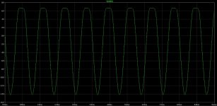
so why it clips positive sine halve @ +6,6V?
any ideas how to set it up?
Attachments
Padamiecki, sorry the circuit in the thread I mentioned is the last one on the page. It uses the grounded emitter idea. It does use feedback but the thd figures look very good.
Last edited:
Padamiecki, sorry the circuit in the thread I mentioned is the last one on the page. It uses the grounded emitter idea. It does use feedback but the thd figures look very good.
I am not an expert but I think that from this current output stage (you mentioned, the last on the bottom) goes voltage nfb which cancells the benefits of this I-output type.
I am not able to open all pages (only the first page).
by post #40 and 41 about
http://www.diyaudio.com/forums/soli...tortion-class-ab-output-stage-topologies.html
you will find the completly article
check out also this thread:
http://www.diyaudio.com/forums/soli...lic-conversion-amplification-hca-circuit.html
Last edited:
Ian Hegglun's Square Law Class A
I've been in contact with Ian Hegglun and he helped me simulate figure 4 from his Linear Audio, Volume 1 article. Ian has also been very helpful answering questions in regard to this circuit. Ian's skill as a design engineer is very impressive; he's put a lot of good engineering practice and thought into his Square Law designs.
Attached are screen shots and LTSpice simulation files. Ian tweaked the EKV transistor models to simulate square law behavior. I'm also using some of Bob Cordell's models.
This circuit will be my next amp project.
Attachments
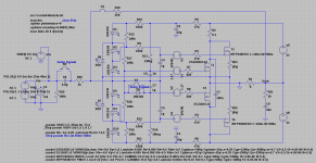

Tiny currents of 150mA peak in T3 + T4 are square law class A.
But much bigger currents of 2A peak in T1+T2 are linear class A.
I don't see where the efficiency is supposed to come from?
But much bigger currents of 2A peak in T1+T2 are linear class A.
I don't see where the efficiency is supposed to come from?
But much bigger currents of 2A peak in T1+T2 are linear class A.
I don't see where the efficiency is supposed to come from?
Which currents are these? With output signal? The bias currents should be much, much lower, so although the circuit 'works' like a class A circuit, the bias current (and thus the eficiency) is of a class AB circuit.
jan
Which currents are these? With output signal? The bias currents should be much, much lower, so although the circuit 'works' like a class A circuit, the bias current (and thus the eficiency) is of a class AB circuit.
jan
The bias current for T1, T2 is 1.13 A when I simulated it, so it is class AB but very deep one. For T3, T4 is 26 mA only. The power dissipation wile idling is 76W and this is not so low.
How to to thermally stabilize this combination of lateral and vertical MOSFET output transistors?
dado
- Status
- Not open for further replies.
- Home
- Amplifiers
- Solid State
- Square Law Class A Amps